• Please review our updated Terms and Rules here

PDP-9 at the RICM

We have found that the PDP-9 format is really picky about DECtapes. You can format DECtapes in PDP-9/PDP-10 format on a PDP-8, but only about 10% of the ones that I have tried will successfully format and go through all of the checking steps. Some DECtapes are too short and go off the end of the tape. Maybe it is just that having been a PDP-8 DECtape for 50 years makes them reluctant to be changed to a PDP-9 format?

In any case, the DECtapes that format and check OK on my PDP-8/e & TD8E seem to work OK on the PDP-9. I can use a modified dumprest program to write tapes that work OK on the PDP-9.

Today I booted ADSS V5A that I sysgenned on SIMH to be configured for 8K of core. The other two TU55 drives held scratch tapes. I used the "N 1" and N 2" commands to write empty directories to the scratch tapes. I used EDIT to create a "HELLO WORLD" program in FORTRAN. That was a learning experience, and too quite a few tries, and really spins DT1 and DT2 alot. We have to use the "abbreviated" F4 compiler because our PDP-9 only has 8K of core. We got the program to compile, and even got a listing of the resulting MACRO instructions. We got stuck getting the LINKER to work. You need to enter the ALTMODE character after the program name, and it wasn't obvious how to get a VT220 to sent that character. Even then it didn't link the file and run it. That is the project for this week.

It looks like this project is finally going into the software phase. Time to get some demonstration programs running.
 
You do know that the only difference between the "PDP-8" format and the <all other systems> format is the size of a block, right?

If you run off the end of the tape, that is obviously a problem, of course. :)
A bit surprised about that, but then again, at format time, all bets are off, and it's all about timing.
Slowing down the reels at format time is a classic trick to get more blocks on a tape. Or maybe you should just format with a few blocks less? But then again, I wonder if a PDP-9 will expect a certain number of blocks to exist on a formatted tape...?
 
You do know that the only difference between the "PDP-8" format and the <all other systems> format is the size of a block, right?

I am using MARK 384 format to make the PDP-9 DECtapes.

If you run off the end of the tape, that is obviously a problem, of course. :)
A bit surprised about that, but then again, at format time, all bets are off, and it's all about timing.
Slowing down the reels at format time is a classic trick to get more blocks on a tape.

Some DECtapes are shorter than others. 3M was known for making tapes that were long enough for a PDP-9, but not long enough for a PDP-9/PDP-10.

Or maybe you should just format with a few blocks less? But then again, I wonder if a PDP-9 will expect a certain number of blocks to exist on a formatted tape...?

The PDP-9 writes blocks in both directions and skips 4? blocks between block writes. When it gets to the end of the tape it turns around and writes blocks backwards. Reducing the number of blocks on the tape would only work it I flagged the missing blocks as being allocated to a file. That would be complicated.
 
I am using MARK 384 format to make the PDP-9 DECtapes.
That, unfortunately, don't mean anything to me. Is it some hardware or software? For which platform?

I do know how the format on the tape looks like. And it's the same for all systems. It's just that on a PDP-8, you normally formatted with 86 18-bit words, which fits 129 12-bit words. Good enough when you want 128 12-bit words in a block.

On all other systems, you format with 128 18-bit words. On a PDP-11, you just waste the two top bits of each word. On a PDP-9 you get 128 words, while on a PDP-10 you get 64 words.
Even and nice...

Some DECtapes are shorter than others. 3M was known for making tapes that were long enough for a PDP-9, but not long enough for a PDP-9/PDP-10.
Right. There were certainly some DECtapes that were a bit on the short side. Which could lead to problems.

The PDP-9 writes blocks in both directions and skips 4? blocks between block writes. When it gets to the end of the tape it turns around and writes blocks backwards. Reducing the number of blocks on the tape would only work it I flagged the missing blocks as being allocated to a file. That would be complicated.
The fact that it wrote in both directions is irrelevant. But if software expects there to be a certain number of blocks on a tape, then you'll have problems if all those blocks don't exist. It could definitely be an idea to fake those blocks as being allocated to a file. As long as noone tries to access that file, you'd be good, and all the rest could then be used without problems. But I agree that this could turn complicated, and is probably not worth the effort. Better format with a shorter lead tape, and/or break the reels slightly when formatting, so they take less physical tape.
On a PDP-11, a DECtape is expected to hold 578 blocks. I would assume it is the same on the PDP-9 and PDP-10. I can't remember offhand how many blocks a DECtape is supposed to hold on a PDP-8, but I think it might have been 1474.
 
Last edited:
The PDP-9 DECtape has 576 blocks of 256 18-bit words.

Doh! Sorry. My brain wasn't working right. Of course it is 256 words in a block, and not 128. Interestingly enough, both code I looked at, as well as the picture of a DECtape cannister claims 1102(8) blocks for non-PDP8, which is 578(10). However, PDP-9 software could certainly just use just 576 of those blocks. That would work without any trouble.
 
Another milestone with the DEC PDP-9 today!

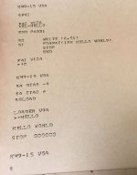
The Teletype printout shows a simple "Hello World" program written in FORTRAN being compiled and then loaded into core memory, linked with the libraries, and run. Once we add the FOCAL interpreter to the system DECtape we will be able to write programs in FORTRAN, FOCAL, and MACRO.

RICM_PDP-9_Fortan-IV.jpg
 
We are running ADSS V5A because the source code is available. I am trying to get ADSS V4E running because it takes a little less memory so it can run bigger programs. All versions of ADSS V4x that I have tried, something like 20 different versions, don't work on the real or emulated PDP-9s. The system loader gets a bad pointer to to the DATs that describe the peripherals so the loader report a bad DAT and dies. That means no system or user programs can be run. I have reconstructed the source for some of the V4E loader using SIMH and the V5A source. It looks like the problem is actually in the pointer passed to the loader by the monitor, so I will have to dig into the monitor source.

I need to document the syntax for the commands and tools that I have working because the syntax is different from the available manuals. I should also sysgen a DECtape image that works well with SIMH and the real PDP-9 and make my notes and the DECtape image available to SIMH users.
 
I tried to boot the PDP-9 last Saturday to make sure that it would work OK for an online demonstration next week. Since it has been very reliable lately I was surprised to find that it didn't even wiggle the DECtapes when it finished reading the bootstrap paper tape. I toggled in a few I/O instructions and found that the processor could interact with the TC02 DECtape controller, and the Teletype. That likely meant that the bootstrap problem was in the processor.

I tried to run the memory checkerboard and it failed miserably with lots of unusual errors. Time to check the basics. I ran Instruction Test #1 and it failed on the rotate left by two bits instruction. I single stepped the failing code and you could see the Link bit get turned on and the AC cleared, and then rotated left. Bit-14 didn't rotate into bit-12. The other rotate instructions worked OK. By studying Maintenance Manual #1 and the corresponding prints I could see that there was only one Flipchip that gated bit-14 into bit-12, a B169 NOR gate using pins K & L. I swapped it with a spare, reloaded the diag, and everything now runs OK.

I checked the voltage drop on all of the diodes and transistors on the defective B169 Flipchip and found a transistor, Q4, with an open Emitter to Base connection. That transistor is connected to pins K & L.

I was a little surprised to be able to debug and repair the machine by running the DEC diagnostics, studying the manuals and prints, doing some simple instructions tests, and using logic to determine the mist likely cause of the failure. A DVM was all that was needed to find the defective component. No 'scope or logic analyzer was needed this time. Pretty cool!
 
Not to mention the idea of fixing the instruction set on your CPU by replacing a transistor.
 
Well, the PDP-9 broke again. I left it running for two hours while I talked to visitors. When I got back to it it had halted and would not reboot ADSS from DECtape.

It has a diagnostics in microcode where it copies data from the MA register to the other registers, increments the value, and copies it again. The incrementing value went from bit-0 to bit-7, but no further. After studying the prints and reading the maintenance manual I decided to try fiddling with the very complicated adder circuitry made from B131 flipchips. I swapped the B131 for bit-7 with the one for bit-8 and the problem moved a bit. We found an open DEC3009 transistor on the B131, and replaced with a real DEC3009 spare from our DEC field service tool kit.

Now the system would run diagnostics from paper tape, but the Basic Memory Checkerboard Test failed with bit-7 in address 013515. Very strange to have two independent problems for bit-7. There are a bunch of flipchips in the memory subsystem that deal with bit-7. We decided to ignore the B169 Mux FlipChip the G009 Sense Amplifier because a failure of these flipchips would cause a problem for bit-7 in all addresses. That left the G219 Memory Selector FlipChips in slots AB09 and EF09 for the bit-7 Digit Drive circuit, and the G219 FlipChips in slots HJ23-HJ30 for the Word Select circuit. PDP-9 core memory is very different from PDP-8 memory in case you were wondering. The next day we started debugging again by running the Basic Memory Checkerboard Test. Of course this time it worked OK, so we let it run for a long time. Maybe it was just a bad connection on a flipchip finger edge that got fixed when we fiddled with the boards? I am sure that we will see this problem again, so maybe we should run the Basic Memory Checkerboard Test every week.

The ADSS OS is booting again. All TU55 DECtapes are a little flakey. We will have to go through the maintenance adjustments to see if we can get them to behave better. At least we can again demonstrate a running PDP-9.

We have been collecting the analog flipchips so we can install the 34H graphics. We will repair a Tektronics R503 'scope and install it in the top of the CPU cabinet. Then we can see about getting Spacewar! running.
 
I am always amazed at you folks keep these rare, nearly 60 year old machines alive!

Our visitors get a very different experience interacting with an ancient machine than just seeing a static display. Seeing their reaction to the PDP-12 running Spacewar! is worth all of the effort.

Getting these ancient machines working the first time is the challenge. There is usually so much that is broken it is difficult to get enough of a response from the machine to determine what else is broken. We don't have a board tester for the PDP-9 and PDP-8/S because it uses negative voltages for the logic, and we have not spent the time to design one. Once we got the PDP-9 and PDP-8/S running the failures have always been a single transistor or diode. A single part failure is not so difficult to track down.

For the PDP-8/I, PDP-8/L, and PDP-12 we made a flipchip board tester, fixed every board we could test, and then did the debugging. That was much easier than testing each part of the machine and fixing things as we found failures. Lots of people on this forum have supported our efforts with donated parts, PCB designs, recovered media, and technical help. We really can't keep the machines running without a lot of help.
 
The PDP-9 broke again last week when I tried to demonstrate the ADSS OS running from DECtape.(ADSS is just a monitor and really doesn't deserve to be called an OS.)

It passed the first of the instruction diagnostics, so most of the machine is working OK. It failed the second instruction test. After digging through the diag code it looks like it turned on the clock, waited for the clock flag to turn on, turned on interrupts, turned off interrupts, and got an unexpected interrupt. I am a little surprised that you can have a pending interrupt, turn interrupts on, immediately turn interrupts off, and not have an interrupt occur. Another interesting thing about the PDP-9 is that the interrupt circuitry is in the I/O controller, not in the processor.

After toggling in some test code I found that the ION instruction enables interrupts, but the IOF instruction does not disable interrupts. It looks like the S202 Flip-Flop in slot J07, or the B213 JAM Flip-Flop in slot F15 has failed. We have replaced and repaired a bunch of B213s, so that will be the first to try this week.
 
We are getting closer to the hardware problem that is preventing the ADSS monitor from booting. MAINDEC-9A-D02A-D Instruction Test Part 2 fails where it turns interrupts on and in the next instruction it turns interrupts off. The User's Manual says that if the next instruction after the ION is an IOT or XCT instruction it will not turn interrupts on. This means that the ION and IOF instruction pair should not enable interrupts.Our PDP-9 is enabling interrupts so it fails the diag.

Now we need to discover how the ION is delayed until the next instruction is not an IOT or XCT.
 
We toggled in a little program that turned the interrupts on, turned the interrupts, read the system status word, rotated the AC left into the LINK one bit, skipped over a halt if the LINK was a zero, and jumped back to the beginning. The left most bit in the status word indicates that the interrupts are enabled and should be off after the IOF instruction is executed.

The program runs OK for several minutes when the system is cold. and then fails. Restarting the system, the program will fail immediately. If we let the system cool off and try it again, it will run OK for a while.

It is time to connect the scope and logic analyzer to the PIE flip-flop that enables the interrupts and see what the signals look like when it is cold and when it is hot.
 
Well, I have been chasing the interrupt problem for more than 20 hours so far. At least now I know where the problem is, and also know way too much about how the processor and the I/O controller interact. This system is way more complicated than a PDP-8!
 
Back
Top