• Please review our updated Terms and Rules here
  • From now on we will require that a prefix is set for any items in the sales area. We have created regions and locations for this. We also require that you select a delivery option before posting your listing. This will hopefully help us streamline the things that get listed for sales here and help local people better advertise their items, especially for local only sales. New sales rules are also coming, so stay tuned.

Pertec ISA interface card

Problem we had is that we use PE drive to read NRZ1 signals. This means problems. PE electronics is not made for reading slowly changing NRZ1 data signals with lots of DC offset and this causes lots of digital noise on data channels (when there is no change in the head current comparators that form digital signals start to freak out).

If you are still using the Qualstar, disable the AGC, or read the data analog just after the preamps.
 
This would be a good thing, as most of the drives capable of 800 NRZI tend to be high-speed streamers (e.g. Kennedy, M4, etc.). I prefer reel-to-reel for data recovery.
 
If you are still using the Qualstar, disable the AGC, or read the data analog just after the preamps.

We're still using the Qualstar drive. For now I am trying to avoid going analog - that would be much harder to do hardware-wise.

As for the AGC tip, I don't think this is it. I'm not sure if I'm reading the schmatic corretly, but this is how I see the problem with NRZ1 signal put through a PE signal path (http://www.textfiles.com/bitsavers/pdf/qualstar/500150B_1052serviceMan.pdf, page 92):

* ZCD signals are outputs of LM319 comparators, that work as 0-crossing detectors
* input of each LM319 is driven by a differential of head signal
* for NRZ1, constant head current is completly normal for long bursts of "0" on a track
* after the differential, this results in 0V on the comparator input
* this 0V is in fact noise that constantly crosses 0V, wchich results in digital noise on the output of LM319

ENV signals, on the other hand, are derived from head signals without the differential in the middle, hence no noise. But there is another problem - analog signals that drive ENV comparators are filtered, thus edges are heavily missaligned. And the nature of missalignment heavily differs from tape to tape (depends on signal levels?).
 
ENV signals, on the other hand, are derived from head signals without the differential in the middle, hence no noise. But there is another problem - analog signals that drive ENV comparators are filtered, thus edges are heavily missaligned. And the nature of missalignment heavily differs from tape to tape (depends on signal levels?).

Let me look at the schematic. In a normal data recovery circuit, the incoming signal is sent through a differentiator before the comparator so that rather than amplitude, it is detecting when the rate of change goes to zero, rather than the amplitude going to zero (zero crossing) to get away from the noise problem you are seeing.
 
Just a quick update: My "software tape reader" finally works nicely. I was able to read all five NRZ1 tapes. 100% correct blocks, although some of them needed manual treatment (more errors than parities could handle). I've just recovered 1433 files in total, 43MB of data. Some files are dated 1973!

Software will be published soon, I will also gladly provide help if anyone decides to use it.
 
Looking forward to seeing some details!

me too! I have a couple dozen 1052s and a few 1260s

this reminds me I need to take pictures of the different versions of pcbs and pertec-scsi adapters qualstar made.

i've got a disassembly of the 105x eprom around somewhere too.
 
Guys, sorry for not updating you on this, I got distracted by too many things in the meantime. :) As I've mentioned earlier, I was able to read all my NRZI with great success.

Restoration was done in two phases. First, a low-level tape images were taken by tapping into 9 head signal paths ("ENV" signals) with a logic analyzer, running all five tapes at a low speed of 50 in/s, and sampling the signals at a rate of 1MS/s (thanks to asbesto from http://museo.freaknet.org/). This resulted in 2.2GB of raw head signal images ready for further processing. To convert the signal data into actual files that were stored on a magnetic tape, custom software was needed.

Problem was that we had to use ENV signals, which are basically "data ready" signals, heavily misaligned (that's on top of track scatter and tape skew). Real data signals ("ZCD") were
unusable due to high digital noise caused by drive/tape format incompatibility (reading NRZI tapes on PE electronics). I had only partial success in removing the noise and eventualy gave up. Signals from ZCD lines would work just fine with a minor drive mod and I guess it's a valid option (resulting in a great, clean input data for further processing!) but I've found a way to "straighten" wobly data pulses in ENV signals and use it to read the data.

All the filtering, straightening, unscattering, deskewing and decoding was done with a tool I wrote - "NineTrack Lab". It's available here: https://github.com/jakubfi/ninetracklab It is by no means a mature nor complete software - it was tested on my five tapes only and I was the only one using it, so there are probably countless UI and usability issues. But it is able to fix just about any fixable issue with NRZI signal. Some issues are corrected automatically, some require manual parameter tuning. If nothing works, signal can be even redrawn manually and then checked against parity/crc to get a perfect block.

Screenshots:

Main window - fragment of a data block with a single parity/crc error marked with red "rulers" (list of all blocks on the right, green ones are decoded without errors):
Tape import window

If you want me to explain anything in greater details - let me know. :) Also, if anyone is interested in using NineTrack Lab I will gladly provide some guidance or even help with the decoding process.
 
Amo,

Nice work here, congratulations! A friend forwarded me your website page on this project, which is how I learned of you. We've already been talking by email at this time, but I just wanted to post here so others could see my comments and support.

You've done fantastic work here, and I love the similarity to my work on reading damaged or unknown QIC cartridge tape data formats at http://QICreader.com

I've now linked your page on my Tributes page QICReader.com

I never used jakubfi/ninetracklab , and didn't even know of it until 2 days ago. But I basically wrote my own code (in LotusScript of all things) to do my own version of what jakubfi/ninetracklab does, so I have effectively "reinvented the wheel" here. But that's OK. I'm happy to share with all who are interested.

And also, I always want to continually extend thanks to Chuck(G) and Al Kossow, for being continually providing help, advice, and inspiration for my QIC projects.

I look forward to comparing notes and collaborating on future projects as they may overlap.

Best!
-AJ
http://QICreader.com
 
Last edited:
Due to some work-related relocation I have been away for a long time and I would like to apologize.

So I'm back in the ancient tape drives neighborhood and I am starting to work to a pertec to serial interface - for the beginning. I think I will start by tricking my qualstar to communicate with an arduino due (80MHz). For now I am gathering documentation.
I read all the posts since I came back - the Mera-400 restoration project is quite impressive. I am trying to do the same with two romanian mainframe systems - Felix M and Coral 4030.

Did you guys manage to build any pertec communication interfaces? If so, may I ask for your assistance?

Also - I would like to find another MCS-1 pertec controller, just for spare.
Also please let me know where I can post the MCS1 drivers and software utilities (including source codes).
 
CHM has been doing some work recently reading the analog preamp output of the Qualstar with a Saelea analyzer in analog form at 765khz
Test tapes containing two files with 512 byte blocks of an incrementing 16 bit pattern were created at 800 and 1600 bpi,
then read on the Qualstar at 50ips.
The digitized samples can be found at http://bitsavers.org/projects/9track.
The 10th channel is the tachometer signal to get an idea of how fast the tape is actually moving.
Uncompressed they are about 2gb and can be examined with Saelea's Logic program without an analyzer.


An analog decoder is being worked on here
https://github.com/LenShustek/readtape

with work being done on processing tapes with extensive dropouts.

Len is making major changes to it right now, but you can see the general direction.

It is also interesting to look at the schematics for data channels in various vendors nrzi and pe encoded tape drives.

Also, I've uploaded spice models of the bandpass filter showing an attempt to flatten the passband to get f (39KHz) and 2f (78KHz) closer in gain.
2f is significantly lower in amplitude on the 1600bpi test tape. If the model is correct, it starts to roll off at 20KHz already.
 
Last edited:
Thank you for the updates.

I managed to read/decode tapes written in !ASCII (EBCDIC) PE@1600BPI by some old French IRIS50 computer clones - made in Romania under French license and called Felix. The data is weird, their programming language was some kind of half-breed between Pascal, fortran and ASM with french mnemonics.
Also I managed to read/decode PE tapes @1600BPI written on another communist-block clone, this time a PDP11.
All these tapes are databases backups. No apps recovered so far.
All the tapes I got were kept in good conditions even if I recovered them from rain and mud at trash dumps. My drive had some trouble reading two of the tapes (those in ebcdic format), it took around 18 hours per tape to complete.
In the mean time I managed to get my communist monster up and running. Access is done via serial console from a BSD Unix. Tape reads and writes are working fine.
https://www.youtube.com/watch?v=EGL1LckjEbo
 
There are lots of old 9 track drives that will do 1600 PE density. I suspect that there are more, like Cipher 880s than there are drives that will do 6250 GCR and 800 NRZI.

Most of my recent work has been handling 7 track NRZI tapes. I can handle all of the common densities (200, 556 and 800 BPI) and have some methods for recovering blocks with errors that seem to be working quite well. I'm using an HP 7970B feeding into a STM32F407 board with Micro SD storage. Other than console interface, it's standalone and takes the raw output of the 7970.

I've thought about doing a similar standalone Pertec interface board using an STM32F429 MCU with 8MB of SDRAM and MicroSD. I've got the board put together, but not wired up or programmed. I'd rather take the raw output before the formatter, however, as 180MHz with 0 wait states is more than adequate to handle formatting operations. For most 9 track stuff now, I'm using my Fujitsu X2444 drive with an ISA Pertec controller.

It seems to me that every time a layer of logic is added to tape processing, a bit of control is lost. So a Pertec formatter hides a bit of detail--and the same formatter hooked to a SCSI interface loses even more. I have a Qualstar 1260S that's just about useless when it comes to getting detailed information about a tape error--and it isn't a great drive to start with.
 
Wow, I clicked on "submit reply" and it refused to submit the text!
Later I discovered this post disappeared and I put it back.
What is happening?

Yes, that is correct.
Pertec is like a Parallel Port with 9 read-data lines, 9 write-data lines, around 6 status lines and around 17 control lines. I don't have the papers with me but you already know how it works.
SCSI layer handles the pertec communication in its own way. The computer just sends and receives data. Sometimes it complains about timeouts and it can set/request the tape density. All the rest is handled by the converter. Error reporting depends on how the converter is implemented - how many of the scsi commands and message can be handled. And this is a big problem. SCSI protocol can not be perfectly implemented at amateur/hobby level.
Because such converters were manufactured for business equipment, they assumed there were enough money for servicing and replacement to be cheaper than the effort to make everything perfect. It is like printer cartridges and toners "counter chip" scam of today.

In the mean time I am back to the drawing board. I have a STM32 development kit (discovery) with no JTAG programmer - out of stock, will arrive later. I am away with work related stuff, in the little spare time I am working to get this thing done.
While awaiting to return home - back to my dinosaurs - I managed to implement the read/write sections of the Pertec communication protocol with a lot of help from all the documentation I could find on bitsavers. Paper pulsing & timing diagram charts. I do not worry about error correcting yet as I have good tapes - one old experiment with VHS tape material went surprisingly well with great results. First I want to see data going in and coming out.

However the fatigue claims its huge share of energy and I am trying to cheat. In order to avoid headaches/schizophrenia/masochism reimplementing the SCSI protocol layers, I concocted some schematics using the NCR5380 scsi controller chip. And I would like to ask for your assistance: did anyone managed to talk to this circuit using the parallel port? I pulled some strings in order to get some of those - both the originals and its so-called soviet union clone.
Please advise.
Thank you.
 
As I mentioned earlyer I concocted the first version of...


"The Pertec Whisperer"


Arduino must talk to the tape drive and must also become a tape drive - jumper selected function.
As soon as I get this done, I will start with the SCSI side.
In the mean time I am searching the e-bay for PCMCIA SCSI cards and an USB-PCMCIA interface.
Because I will need a lot of system restarts and I can not afford that - better plug and play.

pertec_prototype.jpg

Pertec has the following lines:
9 x data output (inverted rd0......ird7 and inverted read parity)
9 x data input (iw0...iw7 + iwp);
14 status lines
17 control lines
3 address lines.

I am not sure about the direction of ISGL (J1-14).

It is an extended version of the parallel port.

However SCSI is more advanced and a dedicated chip is better than reimplementing everything from scratch.
NCR5380 or the Zilog version which is faster.

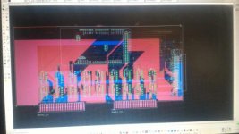
I will be back with the full schematic and full PCB, it is not finished now. Jumper is missing, the arduino is not connected, no power supply implemented.

Releasing the software will depend on how I manage to advance with the scsi side.

Not enough pins? There is another sollution: multitasking layer, two additional SPI lines, some RAM buffer and another arduino handing the SCSI side. Or some port expanders. Arduino Due rocks.
The chips are all 7406. Half of them for talking to the drive. The other half is for becoming the drive.
Arduino Due is fast but not 5V tolerant.

I would like to know which kind of 7406 should I pick. Normal, HCT, LS, N, or A. I need them to be powered at +3.3V, but I need them to accept +5V input - higher than the supply voltage. The soviet version К155ЛН3 (K155LN3) can do it. I will take my chance with my qualstar and see if it accepts 3.3V pulses instead of 5V.

I will save a lot of time and I will get it done faster.
 

Attachments

  • IMG-20180408-WA0021.jpg
    IMG-20180408-WA0021.jpg
    23.7 KB · Views: 2
Last edited:
On the subject of the 7406, I'm a little confused. The 7406 is an open-collector output inverter. Why does it need to have a +5 input if you're driving it from a 3.3V MCU? If you're powering the 7406 from a +5V source, then any input higher than about 2V will be viewed as a "1", so the logic input voltage scarcely matters. As far as current-carrying ability and output voltage ratings, both the '06 and 'LS06 are rated for sinking 40 ma and 30V. So, the only relevant parameter is the input curren (Iil), which is either 1.2 ma for the '06 or 0.2 ma for the 'LS06, hardly making any difference as far as your MCU goes. I prefer to use 74LS07s, as most MCUs reset their outputs as high-impedance, which means that the output of the '07 would also be high, or inactive as far as the interface is concerned.

You may also want to consider a plain old octal buffer, such as the 74LS244, which, although not an open-collector device, has enough drive capability for your purpose and can be "floated" when your MCU isn't active.

My Fujitsu tape drive can spit out 1MBps when it's in streaming mode. I use DMA to handle that, rather than polled I/O.

As far as a SCSI interface goes, I don't see the logic in it. SCSI gives you very little information as to what's going on. For example, if you have a frame wtih an error in it, most SCSI drives will seesaw until the default retry count is exhausted--and then not tell you which frame is in error and which bits are in error. SCSI is one of those interfaces, like USB that works well when everything functions without error, but is very bad news if there are errors to recover from.

A Pertec interface, in my experience is very different from a parallel port. There are signals that are not "latched" during a block--you have to be there to see them. Further, there is no handshaking. If you assert WRITE and you're not ready with data, the drive will simply take whatever is found. Similarly, there's no detection for receiver overrun--the drive just throws data out and you'd better be ready to catch it.

My preference is for an MCU with lots of memory and high-priority DMA. If you need to store or retrieve data from mass storage, there's always SDHC or USB flash, which can be buffered to run in the background.
 
Last edited:
About the signal inverters. The direction of the signal is either from MCU to drive, or from drive to MCU. +3.3V is required for the second case - when the drive pulses with +5V but I need maximum 3.3V for the MCU.
Thank you for the 7407 and 74244 ideas. I will study them today.

First I wish to say this arduino project is just an exercise to understand the pertec communication - to learn how to handle the issues you mentioned now, and you also mentioned them in earlier posts. I have a waveshare stm32 open429i development board on a box under the desk waiting for the game.

Why SCSI? I have a pertec to scsi converter from a qualstar 3200. This converter is hooked to the computer and to my qualstar 1260. I have seen that secrecy about errors. But there are two problems which bother me: there are no more new motherboards with ISA, and no pertec drivers available for old Unix systems to get any "inspiration".
I analised these possibilities:

- build a pci to isa bridge and hope the bios is able to recognize it. Activate pci low level access into some virtual machine, get msdos and network communication to work, hope the drivers can do their job, then hope I can pipe any data transfer between host and the virtual guest - too many unknown variables to handle, and I still depend on an ancient controller with a questionable MTBF which I would like to keep just for special cases;

- build a dedicated interpreter between an ancient, extinct language and a classic language. It may not be perfect but some dedicated LCD display may signal any errors which can give any additional clues when classic Latin fails to meet Hieroglyphic/Cuneiform requirements. I have to start from somewhere. SCSI seems a good choice because I have a dedicated chip which relieves me of extra headache. After I see this working, USB peripheral is the next choice;

This is my plan:
- understand the pertec communication using an arduino to talk to the drive and to act like the drive - I can put things in order faster and get better understanding in a short time;
- translate it to scsi and let a modern bsd/linux machine do its magic;
- translate it to usb and get a beautiful 9 track reel to reel tape-based sequential access memory stick storage drive - bsd/linux machine handles the rest;
- implement everything I learn into the STM32 development board, developing some local error handling functions - slower process because the openstm32/eclipse IDE is huge, complicated, I never worked with that, there is a shortage of documentation and tutorials for the open source side, I can not afford to buy the commercial license and I have a lot of learn.
- keep a dedicated msdos machine to handle the not-so-perfect situations.

And it's a pretty interesting exercise in the age of modern technology.
 
Last edited:
Back
Top