• Please review our updated Terms and Rules here

PET 2001-N screen distorion

FishFinger

Experienced Member
Joined
Sep 19, 2009
Messages
309
Location
UK
I picked up a 32K 2001-N recently, and while everything is in working order there's some noticeable horizontal distortion on the screen. The display is correctly centred and vertical edges are all straight, but characters get gradually narrower towards the right. Characters in column 1 are probably 50% wider than those in column 40.

I know almost nothing about PETs so I'm not really sure when to start looking...

Can you share a photo ?

I know of this http://www.cosam.org/computers/cbm/pet/20090305.html report but Are your symptoms anything like this ?
 
Here's a photo, although the effect doesn't seem so noticable so I drew a slightly exaggerated picture to show the effect.

Aside from that the display is very sharp and stable, and the distortion doesn't change over time.
 

Attachments

  • PET (4).jpg
    PET (4).jpg
    146.1 KB · Views: 2
  • PETscreen.png
    PETscreen.png
    513 bytes · Views: 2
Looks like the horizontal linearity is off.
Some monitors have an adjustment for vertical or horizontal linearity but I don't believe any version of the PET monitor has either adjustment.
There are a couple of metal rings on the yoke that adjust the picture centering and might have an effect on linearity.
I have a feeling it's likely to be capacitor aging though.
 
The linearity is compressed to the right, this indicates a high internal resistance in the H scanning coil circuit. The implication being that either the yoke coupling capacitor has gone higher ESR than it should be or possibly the power supply bypass/filter capacitor on the supply rail that supplies the H output stage. The latter is more likely as the yoke coupling caps are usually special quality, but the power supply caps are not.

Alternatively there may be a saturable magnetic linearity col in series with the yoke's H cols that requires adjustments, though many of these are fixed and it unlikely has been tampered with but not impossible.

The centering magnets on the rear of the yoke have no effect on the scanning linearity, just the overall scanning raster centering.
 
Assuming dave_m has identified the correct monitor schematic back in post #2, checkout the following components:

C716 - power supply. I would also check C713 whilst you are at it.

The LIN inductor is fixed - L703.

The associated coupling capacitor is C715.

Dave
 
C715 becomes C28 then... Note that this is a non polarised (NP) capacitor.

Also, your video board doesn't appear to have a LIN inductor in the same way that the other board did.

If you have an oscilloscope, you will notice the traces are marked at the measurement points.

Dave
 
Hi again,

If you did replace the 10uF non polar capacitor , use a polyester or polypropylene film capacitor, or motor run capacitor, not an electrolytic even of an NP type electrolytic, most are not suited and have too high an ESR.

But looking at your photo of the actual CRT face and what you are seeing with the H linearity, is the inevitable result of not having a magnetic saturable linearity coil in series with the yoke's H scanning coil.

The 10uF (S correction cap) in practice corrects most of the linearity error between center and the right hand side, however it cannot fix the stretching of the scan on the left, immediately after flyback. This relates to what happens after reversal of the yoke's magnetic field.

For an explanation of how this works, one way is to look at early sets that had neither the S correction cap and no lin coil either. Read this article from page 8 onwards, it explains how these linearity defects come about:

http://worldphaco.com/uploads/Sanyo_s_amazing_8-P2_Televsion_set_from_1962.pdf

I think, most likely, there is no faulty component in your VDU, and you are seeing the expected result. However degraded capacitors can aggravate the problem, but most likely when you try others I expect the result will be similar, because what you are seeing is very close to what is expected, without the lin coil.

So I'm saying that your VDU is likely "Normal" and you are a very good observer of linearity defects.
 
Last edited:
So I'm saying that your VDU is likely "Normal" and you are a very good observer of linearity defects.

Hugo,
I think that is a good observation. If fishfinger can not expect a lot of improvement, he should leave the board alone. The screen picture (left photo) doesn't seem that bad for the old type PETs.
 
Hugo,
I think that is a good observation. If fishfinger can not expect a lot of improvement, he should leave the board alone. The screen picture (left photo) doesn't seem that bad for the old type PETs.

Yes, looking at the actual CRT photo, there is very little difference in the H linearity comparing the center and right side on the raster, the implication of this is that the 10uF S correction cap is good and the stretching on the left normal without the Lin coil present.

In a nutshell it comes about due to the associated resistance of the yoke, the current climbs toward the right side in an inverted exponential manner, although in the initial region its fairly linear, the rate of change of current decreases with time, but on the R side it is not unhelpful due to the deflection yoke's sensitivity increasing for greater angles of deflection. However, after flyback, the yoke's field is reversed and the field energy is delivered back to the power supply, by the energy recovery diode, the rate of change of current with time is highest initially on the extreme left and decreases with time toward the screen center. So without a magnetic Lin coil, which provides asymmetric control of the current, it is not possible to correct that small stretch in the scan on the left. But it is small enough that many manufacturers ignored it and didn't bother with the lin coil.

I agree, scan board probably better left alone, but it wouldn't hurt to check the power supply filter caps.

(Commodore seem to repeat the mistake of mis-labelling the polarity of the primary and secondary windings on the small transformer which drives the H output transistor (HOT) in their schematics. Mind you that doesn't cause any trouble unless somebody was trying to figure out how the circuit worked. The point being that when the driver transistor is conducting, its job is to turn off the H output transistor, not turn it on. The HOT is switched on by energy stored in the field of the driver transformer.
 
I replaced C23/C24/C25, but there's no noticeable difference, which is what I was expecting since they are only for decoupling. I don't have a suitable non-polarised cap for C28, so I refitted the original since it was well within spec according to the LCR meter.

Would it be worth trying to fit a linearity coil? I can probably dig out something suitable from my parts box.

You could try one, it would be a type preferably with an adjustment of the permanent magnet within it (many types were fixed at the factory) and made for a set with a similar sized CRT.

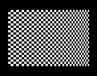
However when the linearity is corrected there will be a loss of raster width, greater on the left than right and the raster centering magnets will need adjusting.

With the width issue, when there is no width inductor, it usually means for the combination power supply voltage, yoke & CRT, that the makers were struggling to get full width and in the case where there is not a suitable tap nearby on the LOPT primary to get more width back, the only way to increase it is to increase the supply voltage to the H output stage, that also increases the EHT, so it is unwise to do that more than about 10 to 15%.

I see there is an unused tap on the LOPT nearby that would have a higher level, possibly that would work with both a lin coil and width coil added, but, I'm not sure, you would need to check with the scope. Also any added width or lin coil ideally has the lowest possible DC resistance. Normally these have fairly thick wire at least 0.5 to 0.7mm diameter.

Overall, since the linearity error is small, I would suggest just leaving it as is and accept it as one of the interesting vagaries of these old monitors.

(On the issue of capacitors being for coupling or decoupling, or the distinction between the application, it makes no difference in power stages like this because power is taken from the supply, via the HOT and returned to the supply via the energy recovery rectifier during the H scanning cycle, so if the internal resistance of the power supply increases, due to aged capacitors, it has similar and near identical effects to the yoke coupling capacitor going high ESR as both introduce resistance into the pathway affecting the yoke current. Usually, for most monitors, the yoke coupling caps or S sorrection caps for the H coils are special quality and don't fail very often, but they more often do for the V coils as they are common garden electrolytic types)
 
Last edited:
Back
Top