Checkout the mains power supply at:
http://www.zimmers.net/anonftp/pub/cbm/schematics/computers/pet/8032/8032051-3.gif. This is pretty much applicable to all PETs.
The tests below are with the PET *** DISCONNECTED *** from the mains supply.
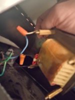
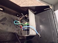
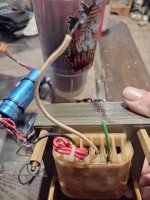
The things in the PRIMARY side of the transformer (mains = lethal side) is the plugtop, the mains cable, the power connector in the PET, the fuse and fuseholder, the switch and the transformer primary winding.
With an intact fuse - and the PET's switch ON - you can measure the resistance (using a multimeter) between the LIVE and NEUTRAL pins of the plugtop. This should be a fairly low resistance. When you turn the PETs switch OFF, this resistance should increase to infinity (an open circuit). This is a good test for the mains side BEFORE plugging it into the mains.
*** WARNING *** Do not hold onto the probes of the multimeter (or the pins of the plugtop) whilst performing this test. The back emf generated when you disconnect the multimeter probes as a result of the collapsing magneting field within the operational transformer will 'nip you'... I usually use crocodile clips (or similar).
If you don't get a low resistance, you can chase the circuit around with your multimeter until you find which component is broken. However, just watch any back emf jolts. They tingle a bit!
Dave