• Please review our updated Terms and Rules here

Pet 4016 Transformer Question

Not necessarily, The 6545 must be initialized on power up by the program. A bad ROM might cause the issue (the code is in the Editor ROM) or perhaps the code is getting lost before it can initialize the CRTC. During boot, there will be 17 writes to the control register of the CRTC to initialize it. Let daver, me and others think about some scope tests to check this out. You may have to hook up a reset switch and use the scope in single trigger mode. This might be a tad hard for a novice with a scope.
 
Cool. This is a new scope for me so the learning curve is a bit step. As for electronic stuff I'm cool with whatever we need to hook up :)

As always thank you so much for the help!

As a side note I have some blank ROM's and a writer on the way. Should be here within the next day or so.
 
If you can find a simple pushbutton or toggle switch with a normally open (NO), normally closed (NC) and a common contact, you would hook up the NO contact to the expansion connector J4 pin 22 (Reset/) and the common contact to ground. J4 is a 2 row connector. Each row has 25 pins with pin 1 and 25 clearly marked so pin 22 should be easy to find. The second row of 25 pins are all ground.
See top assembly drawing for location of J4 connector. http://www.zimmers.net/anonftp/pub/cbm/schematics/computers/pet/univ2/8032090-7.gif
 
As a side note I have some blank ROM's and a writer on the way. Should be here within the next day or so.
In a 4000 series PET, a 2K or a 4K EPROM can be used in the Editor socket (UD7) which is where the PETTEST4 would go. A 2716 or a 2516 or a 2532 EPROM can be used directly. In all the other sockets, you will need 2532 EPROMs directly or a 2732 EPROM with an adapter socket. Not too many new programmers can program a 2532 or 2516 with its requirement for a 25V programming voltage. If it turns out you can not program a 2516 or 2532 EPROM, I can send you a programmed chip since you are fixing a beloved PET.
 
Ok I can do that in a few hours. Not a problem. I have plenty of switches (momentary push button) around :)
 
In a 4000 series PET, a 2K or a 4K EPROM can be used in the Editor socket (UD7) which is where the PETTEST4 would go. A 2716 or a 2516 or a 2532 EPROM can be used directly. In all the other sockets, you will need 2532 EPROMs directly or a 2732 EPROM with an adapter socket. Not too many new programmers can program a 2532 or 2516 with its requirement for a 25V programming voltage. If it turns out you can not program a 2516 or 2532 EPROM, I can send you a programmed chip since you are fixing a beloved PET.
Excellent..... The programmer I have on the way should do 25V but I will confirm that.... being in the US, I would be happy to $$ for shipping also if needed ....
 
Hey all, have not forgot about you all here, been off line a few days with work and catching a amazing head cold... hope to get an update tomorrow :)
 
OK - so I am back to an ample level of health that I can finally jump back onto this....

To recap - The video signals as described in my earlier post with the images from the O-Scope are still holding today... there is no change in any of those....

I have a small momentary push button reset switch wired between J4 Pin 22 and any of the grounds on the second row of J4....

My ROM Programmer has arrived, and I will attempt to write the PETTEST to that tonight and see what I can accomplish using a 2716 ROM in UD7...

If you all have any specific tests you wish for me to conduct, please let me know... I assume I will need to probably look at replacing the UC3 as it might be bad...

Also, I am still not getting the chirp from the pezzo buzzer during any of these power on tests...

Thank you all again so much for you helping on this.... I am humbled and excited to try to get this PET running again :)

Rich
 
Also, I am still not getting the chirp from the pezzo buzzer during any of these power on tests...
Rich,
This chirp happens almost right away within the first dozen instructions, so it is probable the CPU is not running in program. That may mean that the 6545 is not being initialized and may be OK. Let's see what PETTEST4 says if it runs about the condition of your ROM and RAM.
-dave_m
 
Rich,
This chirp happens almost right away within the first dozen instructions, so it is probable the CPU is not running in program. That may mean that the 6545 is not being initialized and may be OK. Let's see what PETTEST4 says if it runs about the condition of your ROM and RAM.
-dave_m
OK , As soon as my set of 2716's arrive, I will have the PETTEST4 loaded and start the diag's.... I will post what happens shortly (The pack is suppose to arrive before Sunday, I will be on a business trip from Monday until Saturday so if they don't get in before then, I will update with some sort of status)

Thanks again to both Dave's!
 
On power up, the Reset Vector will be fetched by the CPU from address $FFFC and $FFFD in the kernal ROM. It will contain the address $FD16 (in BASIC 4) which is also located in the kernal ROM. There, it does a tad of housekeeping like disabling interrupts and initializing the stack pointer, then jumps to address $E000 which is where the PETTEST will start. So if the kernal ROM is able to properly feed a few instructions to the CPU, the PETTEST will be off and running. One of the first things PETTEST will do will be to initialize the CRT Controller with the data constants that set up the proper 20 KHZ horizontal and 60 Hz vertical timing for the video card in the CRT compartment.

PETTEST will not use the stack or any RAM until low RAM is proven good. Let's keep our fingers crossed that the PETTEST code can run.
So I got my EEPROM's as well as the writer - I am currently working on getting a EEPROM written to, but the software that the group has (from MCUmall) isnt working... it continues to crash everytime I attempt to write with it...

As soon as I have this figured out, I will get the PETTEST loaded into the PET and then follow the program to see what is happening ...

More to come :)
 
Crashing does not sound good. On my old Data I/O 29B, with EEPROMs, I do get an error that indicates non blank data, but I only need to start the programming again and it erases the old contents and then programs the new binary.

Let us know the type of programmer you have and someone here may have the latest software.
I got word back from the makers. They told to to remove the computer from the internet to make the writer work. Lol

So now.... I have a few questions.....

1) Pettest2kv4 - is this needing to be adjusted to work on the 40 COL PET? I was reading the document that says it does (the included PDF) if so, I don't have any means to adjust the .bin or hex files :(

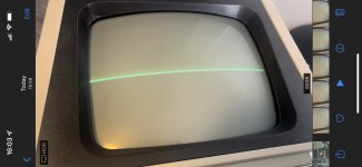
2) I have loaded a copy of pettest2 from the zimmer.net site. Loaded onto a 2716 and inserted it into the UD7 port. Result = nothing. I get a little flicker on the screen but nothing beyond that. The screen is blank unless I hit the reset button. (Then you see a quick scan line) - at one point I saw a bright dot in the center then nothing after that.

So... thoughts? I don't have to do anything special to the EEPROM from an "addressing offset" point of view for these EDITOR Roms do I?
 
C64E1C54-35B2-42A2-96F7-68788033E0FB.jpeg
This is when I press the reset, it flashes for about .25 of a second....

This was with the non-edited pettest2kv4. I also ran the pettest2 file and it resulted in the "dot" in the center of the screen on a push of the reset button.... this "dot" got brighter and brighter then faded. The monitor no longer shows any signs of life.

Aka - flatlined. Lol
 
I am sat in a hotel room at the moment waiting for breakfast, so this will be fairly brief...

You do have a means of patching a BIN file, it is called your EPROM programmer! Load the binary or hex file and there should be some means of manually entering bytes before programming the EPROM.

Failing that, there is an online tool (called HexEdit) that I use. Download the binary file to the Web page, patch the image accordingly and download the resulting binary file back to your computer.

The other way of doing it is to use the source code on my Google drive and the online assembler (asm80.com) to edit the CRTC table and reassemble.

Yes, if you have a 40 column CRTC PET my diagnostic code will not work out of the box.

At the beginning of my diagnostic is a CRTC initialisation table (a few bytes into the code). Pick one of the tables designed for a 40 column machine.

You may need to use the calculator program on your PC to convert from decimal to hexadecimal if you are going to do some patching though.

My diagnostic code can handle any version of PET BASIC. There is a possibility that Eudi's original (and dave_m's CRTC patch) may only work with a subsets of PET BASIC. The difference is the entry point of the EDIT ROM that is called from the KERNAL ROM on a reset.

You need to 'divide and conquer'. You could have a fault on the PET main logic board or the monitor. Disconnect the monitor and 'scope the video and horizontal & vertical drive signals on the monitor connector of the PET logic board. The H and V drive signals need to be correct before you connect the monitor.

OK, breakfast time :)!

Dave
 
Ok cool - I was just looking over various "disassamblers" as I cannot make heads or tails of Hex code. I would not know where to begin to make adjustments as it's just simply a bunch of numbers and letters to me. So I assumed there was something more straight forward. (I do all my coding in C, C+, Python, and Apple Swift.... it's taking me some time to learn about the vintage programming since basic 2.0 is the earliest I ever started playing with programs lol)

The video was the issue we were trying to trace. Since I last have the outputs from the last time it was suggested, the scope shows what I had posted a few posts back. So the video output is no good. I assume then we decided to try to run the PETTEST ROM in hopes it would init the video.... but it would seem that's not likely.

So I'm guessing I have issues elsewhere.... but let me try to figure out how and where to patch the ROM software. Since I don't know much about how the program was written or where to make changes, it might be a hot minute :)

Also, in the PDF file, there was mention (actually a link) to a site that provided some insight to the changes .... the document references cbm-hackers.2304266.n4.nabble.com ---- that site doesn't load.... but it did turn me onto the cbm-hackers mailing list where I have been also to review past posts..... some good reads for sure.

Anyway, I will see about the ROM tonight. And if I don't get far, I will repeat my measurements again to see if anything else is wrong....

Let's say this ROM doesn't bring up anything on the screen.... taking into account all the previous measurements.... would it be worth replacing the video chip? Or do I need to work further back into the system to determine if a new chip would also fail on power up?

Enjoy breakfast and thank you again!
 
Yes, an excellent breakfast (as usual). I stay here a lot!

If you got my PETTESTER from my Google drive there is a fully-commented copy of the source code on there explaining how to do it...

Use the online assembler, load the source file into the assembler and copy the relevant table for the 40 column CRTC initialisation into the correct place (following my comments), reassemble and download the resulting HEX file. No patching required.

Dave
 
Last edited:
Ok let me go grab it from your google drive. I believe I saw a link to it in another thread.

That's a ZIP file of v4 with 4 total files yes? A PDF and then the .bin , .hex, and .a65 ?

Cool.... with it being commented I should not have too much issue. 6502.org link works so I will obtain the proper table info and adjust.

:)

I will let ya know how it goes :)
 
Back
Top