• Please review our updated Terms and Rules here

PET 4032 Issue

robert_sissco

Experienced Member
Joined
Oct 12, 2021
Messages
342
Location
Midwest U.S.A.
So, I have a PET 4032 that is having a few issues that I need help with. I do not have an oscilloscope YET (it is literally in the mail) but one issue I want to tackle first is the power issue. When I cold boot the system, I get nothing. The school district the guy I bought it from got it from has an LED wired into the transformer, and that always goes no, but I will not get anything on screen and no chirp. I let this sit for a few second then power cycle and it boots up "fine" (other issue to come later, I think I need to scope for this). Now I keep rebooting, always comes up. Let is set for a few minutes, I need to to the cold boot cycle again.

This makes me think it might be the big blue capacitor, BUT I have a Tynemuth TinyPET board, the old through hold board designed to go into a PET case, which means I can hook it up to the same power supply I think is suspect and...it books every time. I do not need to do the cold boot warm up then power cycle it for it to boot up no matter how long I let it sit.

I also did check and there is no sign that the big clue blue is leaking, so I am not sure where to check next.

Any ideas?
 
Just before the experts get here, one very common cause of intermittent power / no power / power / no power problems on these is the plug / socket connection between the power supply block and the mainboard. The plug / socket in question usually has the designation 'J8' and it is one particular pin / socket connection in J8 (pin / socket #4) which usually is the problem.

As a beginning, maybe you can (with the power off) unplug the J8 connection and check that all of the pins and sockets of that connection look clean and untarnished, and if necessary clean them up. Also check that none of the solder joints on the mainboard pin row connector have cracked.
 
I agree.

Check the physical connections, cables and solder joints first.

Always use your eyes... A bright light and a magnifying glass is the thing to use.

The next thing will be the /RESET signal. You can test this on power up with a simple multimeter set to read DC volts.

I can explain how to do this after you have performed the visual check.

Unfortunately, the big blue capacitor always gets the blame! However, if the machine hasn't been powered up for years, it could be faulty. Before jumping to conclusions though - let's test it when your oscilloscope arrives.

I am not sure what you are saying about the LED connected to the transformer though/. Perhaps a photograph of where it is connected to will help?

It's been a while since we had a PET to repair...

Dave
Solder joints look good, and like I said the MiniPET has none of these issues when plugged into it, which is why I only originally suspected the big blue, but if the issue are only present on one of the two boards I have to test with, that is leading me to suspect the issue is on the OG PET board and not the power supply.

The reset circuit seems good. I have tested with a logic probe at the CPU and that seems fine when it boots, but I did not have clamps for the meter so I may try the power check since I only have the two hands so I can keep the meter on the pins and flip the power switch at the same time.
 
If you have used a logic probe that is fine.

The key thing should be that the /RESET pin of the CPU (pin 40?) should be logic LOW for a good second or so after power has been applied to the PET.

What colour IC sockets have you got? White?

It is clearly not a 'hard' fault if the machine starts sometimes and not others.

With the oscilloscope we can measure the ripple (low frequency) and noise (high frequency) before and after the voltage regulators to see if we have a power supply problem.

Dave
 
After those usual things like connections, plugs, power supply voltages, the reset etc are checked, and the fault is still there:

It seems from the nature of the fault, that it is possibly temperature sensitive, in that if turned on the first time from an all components cold condition, it won't run. But if the board has been powered for a little while, and the components warm up, it then keeps re-booting reliably each time you try it, until, you leave it off for a good while, everything cools down and then it fails to boot again after that.

A number of parts could be temperature sensitive. Sometimes a crystal can lose activity and be borderline for starting when cold. Just one of the many possibilities for this fault.

You could try an experiment (until your scope arrives):

Use a hair dryer set on low and don't hold it too close to the board, you only want to warm it up a little and gently, not overheat anything, so don't use a heat gun.

Leave the computer off for some time, so its in a cold condition where it will not normally boot. Warm up the area of the board where the master crystal oscillator is first. Then try the cold boot.

Or with the scope, at least double check that when it fails to boot that the master oscillator is running (or not) check the signal though a few gates or flip flops downstream from the actual oscillator circuit because touching the scope probe there near the crystal's connections could make it start. However, if it starts late after the 555 reset timer has finished, it won't boot.

Another experiment could be to get the computer started after the 2nd or third boot, and make it do something like repeat printing of a character on the screen, so its easy to see it is running (rather than just relying in a flashing cursor), and try applying freeze spray to individual components & IC's to see if it stops when any component is cooled down.

When the big capacitor fails (loses capacity), the voltage between charging peaks troughs down and twice line rate ripple starts to break through to the output of the 5V regulators. The first visible thing that happens is that ripple appears in the video output signal to the VDU (because its on the 5V rail), easy to see and in the 9" PETs this also makes the raster scan bounce up and down. One simple way to check is to look at the voltage across the capacitor with the scope on DC Coupling and see if the level is dropping down between peaks to near about 7.5V. (the 5V regulators require a minimum of 7.5 at their inputs) Ideally it should be 9 to 10 V at least to allow for the line voltage being low or fluctuating. Or the other way, power the PET via a Variac and you should be able to drop the nominal line voltage by at least 10 to 15% without ripple appearing in the video, which implies the capacitor is holding adequate charge between peaks and that the capacitor is ok.
 
Last edited:
if the issue are only present on one of the two boards I have to test with, that is leading me to suspect the issue is on the OG PET board and not the power supply.

That is a reasonable assumption but you could still have a problem on the male pin row power connector J8 on the PET mainboard. Just check that those pins are really clean and not tarnished, oxidised or burnt, before moving on.
 
That is a reasonable assumption but you could still have a problem on the male pin row power connector J8 on the PET mainboard. Just check that those pins are really clean and not tarnished, oxidised or burnt, before moving on.
I had before and didn't find anything, but I may break out my magnifying glasses to see if there is a hairline crack I missed (would not be the first time)
 
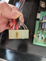
If you're checking power supply issues, take a quick look at the actual connector to the motherboard. My power issue on my 3016 was there and not with the pins itself. It only became obvious when I removed the connector - see attached photo.

Colin.
 

Attachments

  • PXL_20220530_182619698.jpg
    PXL_20220530_182619698.jpg
    1.8 MB · Views: 7
r_s is plugging that same connector into a modern PET PCB substitute and it appears to work, although you can certainly see that the socket receptacle in the J8 / pin 4 connector in your picture had been running hot for a long time at some point. That one is a very good past example of the common fault I suggested should be checked for.

Sometimes the female connector on the end of the cables from the PSU block is OK, but the corresponding male pin on the motherboard pin is dull or black or even burnt.

It sounds as though this one may end up being something else.
 
All the pins on the connector on the board look good, I may try to reflow them and add a bit more solder to them just in case it is something I cannot see. The connector from the PSU looks good, no blackened spots.

Looking my board over I am seeing a single electrolytic capacitor on it. Does anyone know what this is for? I am not sure the age of it, is there a way to tell, are capacitors date stamped anywhere. I bought it refurbished but I am not sure if this was replaced or not from the seller I got it from.

The other issue I am seeing are the voltage regulators in the giant heatsink back near the power supply, is there a chance these may be failing?
 
The problem here is going to be catching it in the act - you'll need to make some measurements when the fault is present, although you seem saying that it is reliably unreliable when first powered on - if so that will be quite helpful. Genuinely intermittent faults are an absolute nightmare to fix, so consider yourself fortunate not to have one of those. If you are not sure where to measure the supply rail voltages and basic CPU signals on your machine, I'm sure the regular PET posse will be able to help you there.

Don't go changing capacitors, etc, without a logical reason to do so - trace the fault, then fix it.

Does your 4032 have a little tinplate box down beside the speaker / buzzer near the corner of the PCB, or is it one of the ones which doesn't?
 
You need to tell us what the component ID is of the capacitor you want to know about (e.g. Cnn). Or end a photograph of it on the board so I can track it down.

Capacitors do have date stamps (lot codes) but they are somewhat obfuscated by the manufacturers and I hate looking them up!

You can test the voltage regulator with an oscilloscope on the power rails (as I stated in post #5). Let me know when you want to do this and I will explain the process.

Dave
 
The problem here is going to be catching it in the act - you'll need to make some measurements when the fault is present, although you seem saying that it is reliably unreliable when first powered on - if so that will be quite helpful. Genuinely intermittent faults are an absolute nightmare to fix, so consider yourself fortunate not to have one of those. If you are not sure where to measure the supply rail voltages and basic CPU signals on your machine, I'm sure the regular PET posse will be able to help you there.

Don't go changing capacitors, etc, without a logical reason to do so - trace the fault, then fix it.

Does your 4032 have a little tinplate box down beside the speaker / buzzer near the corner of the PCB, or is it one of the ones which doesn't?
My other major issue with this PET *IS* intermittent. I happens almost everytime, but WHEN can change. But I want to get it to power on reliability first. I am tackling this one first since I can repro it on demand almost everytime I need to.

I was just asking since it was near the power regulators so it was just something I was looking at, I don't just go changing out capacitors without reason.

Mine has a tin plate in it by the speaker.
 
You need to tell us what the component ID is of the capacitor you want to know about (e.g. Cnn). Or end a photograph of it on the board so I can track it down.

Capacitors do have date stamps (lot codes) but they are somewhat obfuscated by the manufacturers and I hate looking them up!

You can test the voltage regulator with an oscilloscope on the power rails (as I stated in post #5). Let me know when you want to do this and I will explain the process.

Dave
Yea, I can see the lot code, I was hoping there was something easier to determine dates codes with.
The component number is covered by the capacitor itself, but since the ceramic ones on either side are C4 and C6, I am going to assume the one I am looking at is C5. It is a 25V 4700uF.

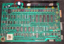
This is not my logic board, I do not have a smart phone or a high quality digital camera, but this is the same board I have and I circled the one in question.

PETMB.JPG

Also, to answer an earlier question you had rereading this, I have black sockets, a mixture of dual-wipe leaf and round hole machined pins.
 
I highly doubt if that electrolytic capacitor circled n the photo above has anything at all to do with your fault.

Re-read my previous post about what to try with the fault condition you have. It is almost certain to be a thermally related issue. Not a bad connection, poor solder join or a bad IC socket either. If it was it would not be following the predictable pattern you have observed.
 
Thanks, so the key bit of information on the photograph is the assembly number 8032089 which identifies the board as a universal 2. It also has the metal box.

I agree with Hugo at this point. C5 is on the input side of the +12V regulator. There are plenty of other electrolytic capacitors on both the input and output of the +12V regulator - and they are all just as important as the circled C5 (to an extent).

I seem to remember you having an oscilloscope?

If so, measure each of the power rails (+12V, +5V and -5V) in two modes:

1. DC coupled looking at each power rail with a relatively slow timebase (suitable for the mains frequency - so 5 ms/div or so. You are looking for the minimum and maximum voltage in these cases. Post the min and max for each voltage rail.

2. AC coupled with a high sensitivity. The nominal voltage should be 0.0V and any noise will now be displayed. Increase the sensitivity and sweep the oscilloscope timebase from slow to fast. Again, you are looking for the minimum and maximum voltages of the noise. The minimum (in this case) will be negative of course. Post the results. You WILL see noise, the issue is "how much".

This will give the voltage regulators and capacitors a clean bill of health (or not).

Are you able to burn a copy of my PETTESTER into an EPROM?

Dave
 
So, checked the power connector pins on the MB with a magnifying glass rather than just naked eyeing it as I did before, still don't see any cracks even when I try to move the pins with my fingers. Still, broke out the leaded solder and the soldering iron and reflowed and added a bit of fresh solder, checked to make sure nothing was bridged, it all looked good. Took it back upstairs, connected power, flipped the switch and...got the beeps on a cold boot.

Put it back in the case, connected the monitor and keyboard, let is sit for 10 minutes, and a successful cold boot.

Thank you for the help everyone
 
Back
Top