• Please review our updated Terms and Rules here

PET 4032 restoration

It doesn't show garbage, but then, there is a ~300ms delay before the screen settles. During this time it shows a horizontal line. On a non CRTC PET that time is when you'd see the garbage. This is my first experience with a CRTC PET so I'm not sure what to expect.
 
It doesn't show garbage, but then, there is a ~300ms delay before the screen settles. During this time it shows a horizontal line. On a non CRTC PET that time is when you'd see the garbage.

Try it a couple of times when the tube is warm. If no characters at all, your video signal may have a problem. You should fix that first so you can tell when you fixed the next problem. Do you have a scope?
 
Yes, Dave. It's a Rigol DSO, the DS1054 with the 100hz mod. I've used it extensively fixing a Philips computer, but never with video signals.

But I can see the scan lines and fly back lines. Doesn't this mean the CRTC is constructing a video signal? Or do you mean there is no data for a dot clock signal to lay the pixels down?

Much guidance is needed here... :)
 
No. It means that the CRTC is generating sync, and that your brightness control is set too high (or there's a complete disconnect somewhere between the CRT's control grid and the video amplifier's input).
 
Last edited:
But I can see the scan lines and fly back lines. Doesn't this mean the CRTC is constructing a video signal? Or do you mean there is no data for a dot clock signal to lay the pixels down?

As KC says, your CRTC is being initialized correctly to give horizontal and vertical timing signals, but the video data comes from the character generator and a shift register clocked at 8 MHz. There may be a problem there. See the schematic page I referenced on my last post: http://zimmers.net/anonftp/pub/cbm/schematics/computers/pet/univ2/8032087-08.gif.

Follow the video signal back from the top right corner. It is 5 V TTL level. You might want to use the 60 Hz 'vertical drive' as scope sync or to use on another channel. There may be only a little pulsing activity on the video signal but it should not be stuck at either high or low. The dot clock is 8 MHz so the DSO sampling period should be set at 100 nS or faster. Hopefully the problem is here on the main board and not on the video board as KC mentioned.
 
When you turn down brightness control can you extinguish the display? If not does it vary brightness at all?
The control is usually fed by a negative voltage like -30 or so. Do you measure a negative voltage on control?

Larry G

PS - I was trained to fix the easiest most obvious symptom first :)
 
Last edited:
@Larry - Yes. I turned it up a way so I could see that the screen is powered / working.

@Dave: I'm gonna "scope it out" as soon as I can - thanks! That probably means over the coming weekend.

I also have enough parts here to build a composite video adapter, but I'm not sure it'll work with an 80 column display (I believe this machine has been modified for 80 cols - it's a Fat 40 as stock).
 
Last edited:
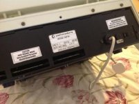
Entirely by accident. I rested the stickers on the foil backed card that the 4032 has screwed to the underside of the keyboard, and thought "eh up... That looks better!"
 
Ah. Just a quick thought.

If I get the boot up chirp (triple chirp in my case) but ?chr$(7) doesn't make it beep and neither does holding a key down for a minute, is it really worth probing the video logic (on the grounds that something is dead further up the chain)? Also, isn't there a test where you take a chip out (character rom, maybe) and get a chequerboard pattern?

Removing the video RAM sends $FF to the character generator which should give a checkerboard pattern. Removing the character generator should output all 1's into the shift register would give a blank screen or an all green screen, I forget.

I worry that since you never see a garbage screen with a warm boot, that there may be something wrong with the video signal.
 
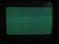
I thought of a quicker way to test the video. Set one of the data lines on the character ROM high. The result should be a repeated character on screen. So I connected D3 (pin 13) to +5v (pin 24) on the ROM chip and the result was this:

image.jpg

It's rock solid, and proves we have an 80 column upgrade installed. The image needs to be adjusted, of course, but that can wait.

Looks like I have some reading to do. Old threads and the like. Meanwhile, I attempted to get into the monitor using the User Port diagnostic line but nothing happened (no beeps, blank screen). Bad, bad, bad.
 
Last edited:
I'm checking round the video generation circuit with a logic probe just to be sure.

Schematic is http://zimmers.net/anonftp/pub/cbm/schematics/computers/pet/univ2/8032087-08.gif (although my board is actually an 8032089).

The 2114 video RAM has pulsing on all data and address lines.
UB4 / UB5 outputs are pulsing (generates BD0-7 bus)
Video latch outputs are pulsing (UB8 latch Q1-Q8 ) as are the CLK and LATCH signals (pins 1 & 11 respectively).
I know that video generation is working forward of the character ROM (see my previous post).

So I can't see any stuck lines. Another quick test I have done is to stick one of the RAM lines low (pin 11 of UC4). This gives a pattern of reverse character blocks with spaces between them that appear to contain a very rapidly changing character (like it is cycling through the ROM or something, can't tell, it is very fast).

I tried a different pin on the RAM (UC4 pin 13) and got a solid pattern of @ characters with spaces between them).

I might draw from this the conclusion that the video RAM is bad, save that I can see a write pulse when the PET boots up (clearing the screen?). My only worry is I get no garbage screen, but the screen itself doesn't start showing a raster until after a short while - does it initialise the CRTC before or after clearing the screen RAM?

I reckon we need to go up the chain a bit here, to see why it isn't booting (not to show the prompt, but to respond to the PRINT CHR$(7) test).
 
Just having a look at the ROM sockets.

UD6-UD10 are soldered to the board with the exception of UD7 which is socketed and contains the Microport 80 column editor ROM. According to what I have read, UD6-UD10 represent the complete BASIC 4.0 ROM set. However I also have a ROM at UD11 and I have no idea what it's for. It's socketed and non standard (an EPROM) and has a torn lable on it "PM96" then "10B132" (that last might be truncated as the label is torn), then a copyright "(c) 198" (label torn). I think it might be a good idea to remove it...

Edit: It's out, the PET is still chirping but still nothing on screen. I'm going to leave it out for now - need to find out what it is.... save it for later. I also removed the Microport ROM to clean its legs. Without it there's no chirp at boot, so perhaps it's OK. Anyway, cleaned and reinserted I get a chirp but again still no screen.
 
Last edited:
These are the ROM images...

View attachment 4032 PET ROMs.zip

None are standard mask ROMs. I suspect the Character ROM was either supplied with the Microport 80 column editor ROM or is a copy of a standard Commodore 8000 series ROM. The PM96 ROM is anyone's guess...

I used the 2732 EPROM setting on my TOP853 programmer to read them as it doesn't have a 2332 option.
 
UD6 = Kernal $F000
UD7 = Editor $E000
UD8 = BASIC4 $D000
UD9 = BASIC4 $C000
UD10 = BASIC4 $B000
UD11 = optional $A000
UD12 = optional $9000

so you don't need UD11 and UD12 to boot, this is why they're usually socketed. I decided a while back that the reason UD7 was socketed was to give the capability of an easy change to a different keyboard layout. If you only have UD6 in you should get a TIM prompt since it will drop to the monitor if no BASIC is found.

(I'm having equal amounts of fun with my 2001 with the schematic not matching what I see on the board)

W
 
Sounds like either UB3 is bad or "VIDEO LATCH" is in the wrong state at the wrong time.
 
>the screen itself doesn't start showing a raster until after a short while

Can't you just leave on to warm up the tube then turn off/on quick to reset with a warm tube?
 
Yes, and I tried that several times. I agree the video RAM might be bad, but that wouldn't stop it beeping when entering PRINT CHR$(7) would it? That would make it beep wouldn't it?

UB3 is the video latch and it does appear to work (per the video RAM test that shows the @ characters).
 
Last edited:
Back
Top