• Please review our updated Terms and Rules here

PET and CBM no video

Forget replacing resistors!

Exactly what machine(s) have you got for repair?

A PET/CBM what? There are multiple variants of these machines...

As you joined very recently, welcome to VCFED.

Dave
 
The biggest mistake people seem to make is going to you-tube and getting advice which does not relate to the fault/s they are trying to repair in their own computers.

There may well be some faults that have a propensity to occur in all of the same models of any type of computer, but even making that assumption, there is no way you can be certain that any repair of a computer, even the same model as yours, is definitely applicable to your machine's problems. So, if you do what they tell you to do in the videos, you can end up needlessly replacing parts, possibly introducing more problems, and making things worse.

Also, if you describe a fault like "no video" you need to be very specific about it , not just for your own sake trying to find the fault, but to help others on the forum try to help you too.

If the remark just means you cannot see anything on the VDU, the first thing is to determine is where the fault basically is.

Has the VDU failed, or is the computer board simply not generating the required signals to the VDU and the fault is on the computer board.

That is a good start.

When you know where the problem is, generally then you home in on the fault with diagnostic tests, using the meter, scope and logic probe if required and support from ROM programs like the PETTESTER and ROMULATOR tools designed to help locate faults in PETs. Always starting with the basics, checking the power supplies first, and then various sub-circuits.

Ideally no parts should be replaced on hunches (or any you-tube suggestions), the only replaced parts should be on the basis of failed tests.

People often wonder why they seem to get nowhere with repairs, usually it is because no logical approach is used, no diagnostic pathway is followed, random stabs in the dark are used to replace parts and the board gets multiple traumas from the various misguided interventions.
 
A very basic bit of information helps.
I can't read a schematic, but I can read voltage, continuity and use a logic probe.

I just need to know what to be checking, and what the normal values should be.

Maybe this is the wrong place to ask.
 
No, this is the correct place to ask...

You are looking for the HDRIVE, VDRIVE and VIDEO signals on the connectors/cable between the logic board and the monitor.

They are TTL levels. You can try the logic probe and multimeter to see what you see, but an oscilloscope is the correct piece of test equipment you require.

I am on a business trip at the moment, so I only have limited access to information until I get home...

Dave
 
Last edited:
I don't own an oscilloscope. It seems nobody agrees upon what is required in an oscilloscope so recommendations of which one to buy that has only what is needed for Commodore (PET/CBM/Vicg20/C64) is all over the place. In other words, people flexing useless information.

Is there a non-schematics document of what I am testing - with pictures indicating specifically what to connect the probe/multimeter to? And what the readings should/ shouldn't be?

I'm reading a lot, but so far nothing specific that I can actually act on.
 
The VDU generally connects to the main computer board with a plug. There are a number of wires, some are earth connections, three of them carry the signals Daver2 was talking about.

Obviously for the VDU to work, the three signals have to be present and the VDU powered and working too.

Generally to find where these wire/connections are on the physical plug, people look up the schematic/wiring diagram of their particular computer model on the Zimmers website and the topographical board layout.

When you have found those connections, which you could now call "test points" if you like, you have to assess the signals there, and really they are better examined with a scope so you can see them and check they are correct. The waveforms that should be there are also in the manuals on Zimmers. A meter won't tell you a whole lot, it may give an average indication of the voltage (that depends on the duty cycle of the pulses) but is not that helpful. A logic probe will show there are pulses there, but not if they are correct.

There are literally dozens of different scopes that could be used to view the pulses, both digital and analog types. For scope beginners analog ones are easy to master, you would simply get one that has a 20MHz bandwidth spec or more, use x10 probes to avoid loading the circuit points you are testing and keep the scope on DC coupling unless measuring small noise voltages on lines with a high DC offset.

One thing is for sure, electronic servicing and vintage computer repairs is all about being able to read & follow schematics. This combined with tools for testing circuit points with scopes and understanding the Physics of the components involved, resistors, capacitors, inductors ,diodes transistors and what logic IC's are supposed to be doing from their data sheets & truth tables and the principles of voltage current, & power. Then with the results of testing, formulating a theory on what has gone wrong and testing the theory.

Expecting to be able to repair something complex as a computer at the pcb/component level without this, is like a person thinking they can fly a plane safely without learning the Physics of flight and having many hours or years of training.

Therefore, there is no such thing as a "non-schematics" document or way of repairing electronic faults in vintage computers, unless it is just dumb luck swapping parts, changing pcb's etc in the hope of fixing a problem.

There was a school of thought in the days of TV repairs, that untrained people could fix them, if they carried spare working pcb's in their trucks and just swapped boards out until the TV started working (they got nicknamed Board Jockeys) Of course it resulted in whole boards being replaced where a lot of the time it was only a 50c part on them which had failed.

For those who don't understand or have experience with electronic theory, there can be a tendency for them to over simplify it. For example, many years ago, when I was working in the TV/VDU repair business a friend who was non-technically minded said, "that must be a pretty simple job". I said how do you figure that ? He replied; well don't you just follow the wires and see what's wrong ?
 
Last edited:
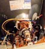
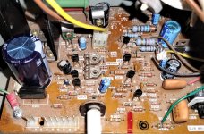
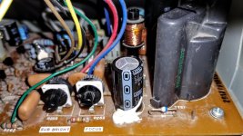
To shorten the diagnostics, I connected a working 8032 to the monitor, and the tube at the back lights up but no picture.

I then connected the SuperPET to a working 8032 monitor and it worked perfectly.

This narrows it down to the monitor.

What can I check with a multimeter?

Note, lit tube is the bad one that isn't working, connected to working CBM 8032. Same result with working SP9000.
 

Attachments

  • IMG_20240117_123355858~2.jpg
    IMG_20240117_123355858~2.jpg
    715.4 KB · Views: 4
  • IMG_20240117_124004641~2.jpg
    IMG_20240117_124004641~2.jpg
    1.8 MB · Views: 4
  • IMG_20240117_124014881~2.jpg
    IMG_20240117_124014881~2.jpg
    1.9 MB · Views: 4
Good part-swap diagnostics there...

You have a SuperPET. Envy!

One thing that Commodore used to do was stuff whatever they had available into a machine so that machines rolled off the production line to customers as fast as they could...

What we now need to do is to identify exactly which monitor you have, and thereby identify the correct schematic. Are there any assembly numbers either marked on the top (or etched into the bottom) of your monitor PCB? For example, something like 8032034?

There are some fusible resistors that can fail with age. But (to point you at the parts on the PCB) I will need to identify the schematic to identify the resistor component identifiers for you to check.

Dave
 
I normally leave things to Hugo and Dave but if It’s the monitor r752/753 should be checked… they fail often .. and go open circuit … encountered that several times. They act as fuses. measure them with your meter for their resistance value … though you may have to remove them or one leg to get a proper reading

this post should help

 
Good part-swap diagnostics there...

You have a SuperPET. Envy!

One thing that Commodore used to do was stuff whatever they had available into a machine so that machines rolled off the production line to customers as fast as they could...

What we now need to do is to identify exactly which monitor you have, and thereby identify the correct schematic. Are there any assembly numbers either marked on the top (or etched into the bottom) of your monitor PCB? For example, something like 8032034?

There are some fusible resistors that can fail with age. But (to point you at the parts on the PCB) I will need to identify the schematic to identify the resistor component identifiers for you to check.

Dave
I am replacing the monitor with a spare from a 8032.

The CRT circuit boards on the 8032s and SP9000 are the same from what I can tell. At least they appear identical. I will take a look for part number.

So far I have one 4032, one 8032.andnone SP9000 working as they should. 4 more to go.
 
On mine, the connector on the PCB of the monitor developed cracked solder joints, you may want to check those or just reflow them as preventative maintenance
 
Good part-swap diagnostics there...

You have a SuperPET. Envy!

One thing that Commodore used to do was stuff whatever they had available into a machine so that machines rolled off the production line to customers as fast as they could...

What we now need to do is to identify exactly which monitor you have, and thereby identify the correct schematic. Are there any assembly numbers either marked on the top (or etched into the bottom) of your monitor PCB? For example, something like 8032034?

There are some fusible resistors that can fail with age. But (to point you at the parts on the PCB) I will need to identify the schematic to identify the resistor component identifiers for you to check.

Dave
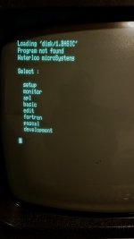
The SuperPET is working great.
I'm at the part where it asks for the disk to load the languages.
I found the link to Mike's site with the disk images. Do I need to add them to my PET2SD?

I had thought the languages were all stored in a ROM on the SuperPET. It's disappointing if I have to load them from disk.
 

Attachments

  • IMG_20240117_193938339~2.jpg
    IMG_20240117_193938339~2.jpg
    1.1 MB · Views: 5
In regards to loading WATCOM software (basic, Fortran, etc.), I just read on TFW8B that the SD2PET doesn't support SuperPET. I really don't want to use a disk to load languages. Any other known options?
 
Cant see why the SD2PET wouldn't work with the SuperPET as it uses the same IEEE-488 port as any other PET and presents it as an edge connection (unlike the SK PET's). The SuperPET works with an 8050 disk drive so should work with the SD2PET I would have thought.
I wonder if its supplying power thats the issue but it has the standard datasette port ?

All the Disk Operating System is within the drive itself, not the PET.
 
Last edited:
The challenge with the Tynemouth SD2PET is that the superpet files are contained in .d64 images …. You can open the image in basic fine but when you flick the switch to go to 6809 mode the Sd2pet resets also and haven’t figured out yet how to open a .d64 image in the native mode. You would need to extract all the files out of the image so your directory listing gets very large.

Do you have a Sd2pet ?

I use a PETsd+ but built it myself.

Steve Gray also has a scaled down simpler version but it means building up your own board (Contact him for advice … I know he is relatively local to you)
 
Last edited:
Cant see why the SD2PET wouldn't work with the SuperPET as it uses the same IEEE-488 port as any other PET and presents it as an edge connection (unlike the SK PET's). The SuperPET works with an 8050 disk drive so should work with the SD2PET I would have thought.
I wonder if its supplying power thats the issue but it has the standard datasette port ?

All the Disk Operating System is within the drive itself, not the PET.
That's essentially what I believed as well. TFW8B states it's not compatible. I have one here, and when I get time I will see if it works. I think it only works in 6502 mode.
 
It think it works in 6809 mode but you have to extra out the images into the root directory. Then I think it will work
 
Back
Top