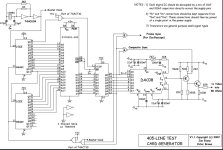
While drawing the circuit in KiCAD to make a PCB, I realised that you can put 5 video images in the ROM in successive Data bits (D0 - D4) as they all share the same H-Drive (D5) and V-Drive (D6) signals. Switching between them, gives you 5 different test images within the same data file.
.

.
So, a bit frivolous, but if you can automatically switch between them, you could create simple animations. Did this one just for fun
")
Basically I wired up a electronic switch in place of SW3 in the circuit above, using some components I had in the workshop (4017 and 2 x 4066s). My clever friend made 5 images of the ball below, offset by the correct angle to create a spinning ball animation.
.

.
Couple of notes on the circuit:
- Clock is 1MHz which gives you a 1us resolution, which is fine to draw typical static test patters. It does mean the 9" monitor will have an effective resolution of 40 x 200, so graphics like this spinning ball will not look very good. Every doubling of clock will also double the horisontal resolution but then leaves less space for multiple ROM images.
- Added Dip-switch selectable inverters on the output signals, if you ever need to invert any of the signals.
- Added support for MDA, CGA and EGA (still untested).
- Board will work with any 1, 2 or 4Mbit EPROM, Flash or EEPROM. The bigger the ROM, the more test images/monitors can be supported.
- With a 4Mbit ROM, you should be able to get 8 different timing maps, so you can support up to 8 different kind of monitors. So far, for PET, I've got 9" 60/15625, 12" 50/20000, and will add 8298 and 700. For PC monitors; MDA, CGA and mode 1 and mode 2 EGA. If you use a monochrome monitor, you can select 5 different video outputs, so - in theory, you can have up to 40 different images for a single monitor. A bit silly, but it just worked out that way.
.
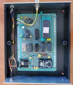
PCB is done (first time I ever used KiCAD, so was a bit of a learning curve - be kind with the feedback on everything I did wrong!
). Once built up and tested working , will publish all the files.
.