• Please review our updated Terms and Rules here

PET Video Generator

Jannie

Experienced Member
Joined
Feb 5, 2017
Messages
273
Location
Cape Town
Got a couple of PET monitors to repair. To make this easier on the bench, the idea is to make a circuit that will generate a video pattern, allowing the monitor to be repaired without having a PET motherboard involved.

/full disclosure: The last time I worked, in any anger, with analogue monitor/TV signals was in the early 80's as a junior tech at the local broadcast corporation. Whatever I knew then have long since been lost in the mist of red wine.

Whatever information forum members can share on how to generate the correct signals for both the 9" and 12" monitors, would be greatly appreciated.

Using information @Hugo Holden posted, together with measurements I did on a working 2001, I got the following for the 9" display:
.
- V-Sync: A negative pulse of 1.25ms, every 16.667ms (60Hz)
- H-Sync: A positive pulse of 24us, every 64us (15.625KHz)

Observations from looking at the 2001:
.
- H-sync seems to go high, about 4.8us after V-sync goes low. I'm not sure if this is required or an artifact of the PET circuit.
- Video seems to start about 20us after H-sync goes high.
- A full line of video seems to be about 40us.
.
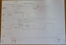
Signals-01.jpg Signals-02.jpg
.
Using the above, I made a signal generator using an Arduino. It seems to "mostly" work but really because it was a monkey-see, monkey-do effort, not because I know what I'm doing. Getting a lot of artifacts and what looks like "analog noise" but must be some errors in generating the signal.
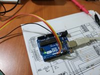
20230528_121921.jpg 20230528_121827.jpg 20230528_122110.jpg
.
Couple of questions:
.
- Horisontal is not a multiple of Vertical; how does one keep them in sync? Is it necessary to keep them in sync?
- Should V and H start at the same time? I measure that H triggers about 4.8us after V. Is this correct or can they start at the same time?
- Where, in all of this, should the video signal be generated?

Any info would be greatly appreciated.
 
Got a couple of PET monitors to repair. To make this easier on the bench, the idea is to make a circuit that will generate a video pattern, allowing the monitor to be repaired without having a PET motherboard involved.

/full disclosure: The last time I worked, in any anger, with analogue monitor/TV signals was in the early 80's as a junior tech at the local broadcast corporation. Whatever I knew then have long since been lost in the mist of red wine.

Whatever information forum members can share on how to generate the correct signals for both the 9" and 12" monitors, would be greatly appreciated.

Using information @Hugo Holden posted, together with measurements I did on a working 2001, I got the following for the 9" display:
.
- V-Sync: A negative pulse of 1.25ms, every 16.667ms (60Hz)
It's 1,280us low out of a 16,640us period to be exact so, in fact, a Vertical period is exactly 260 times the Horizontal.

- H-Sync: A positive pulse of 24us, every 64us (15.625KHz)

Observations from looking at the 2001:
.
- H-sync seems to go high, about 4.8us after V-sync goes low. I'm not sure if this is required or an artifact of the PET circuit.
5us exactly. I don't know if that relationship is necessary.
- Video seems to start about 20us after H-sync goes high.
- A full line of video seems to be about 40us.
The video data starts 18us after H-sync goes high in my simulations and observations. And, 40us corresponds to 40 characters across the screen.
.
View attachment 1258173 View attachment 1258174
.
Using the above, I made a signal generator using an Arduino. It seems to "mostly" work but really because it was a monkey-see, monkey-do effort, not because I know what I'm doing. Getting a lot of artifacts and what looks like "analog noise" but must be some errors in generating the signal.
View attachment 1258176 View attachment 1258175 View attachment 1258177
.
Couple of questions:
.
- Horisontal is not a multiple of Vertical; how does one keep them in sync? Is it necessary to keep them in sync?
Vertical is an exact multiple of horizontal, 64us x 260 = 16,640.
- Should V and H start at the same time? I measure that H triggers about 4.8us after V. Is this correct or can they start at the same time?
To be exactly like the original circuit, H should go high 5us after V goes high. I don't know if the monitor cares. Might be a fun experiment.
- Where, in all of this, should the video signal be generated?
After V-drive goes high, there are 20 blank lines (20 x 64us = 1280us) and then VIDEO_ON/SYNC goes high which signals the start of the active rows (the monitor doesn't see this signal). 5us later, H-drive goes high. The first of the video data goes out 18us after that.
So, the first valid video data starts at 1280 + 5 + 18 = 1,303us after V-drive goes high. All these numbers are exact multiples of the 1Mhz clock that most of the video circuit runs on.
Any info would be greatly appreciated.

I once tried to do a video test pattern generator in an Atmel ATtiny or something. I'll see if I can dig up the source code.
 
Thanks @tsky and @daver2, the fact that V is indeed a multiple of H makes a *lot* more sense. The 60Hz / 15.625KHz not being an integer had me scratching my head.
.
I did get most of the numbers you mentioned in my measuring, but great to find the exact values and why they are what they are!
.
Thomas, do you have similar numbers for the 20KHz/50Hz 12" monitor?
 
Last edited:
Those necessarily use the CRTC, right? No, I have no experience with CRTC PETs.
Yeah, they will be based on the CRTC with a line frequency of 20KHz and vertical of 50 or 60Hz. Will do some measurements when I put one back on the bench. The links @daver2 poste to the CRST setup, might be useful as well.
 
Part of this relates to historical monochrome Television, which is an interlaced system. In the UK the field rate (which corresponded to the vertical sync rate) was 50Hz and in their 625 line system the H scan and H sync rate was 15625 Hz (64uS). So that if you divide that in you get 312.5 lines, the half line required for the interlace.

In the USA vintage monochrome TV the vertical rate was 60Hz and the H rate 15750 ( H = close to 63.5uS & these changed a little when color NTSC got introduced) so this gave 262.5.

Of course not all the lines were active picture lines due to the vertical blanking and H blanking intervals which corresponded t the beam flyback. In the USA system the H blanking was 0.16H or close to 10.16uS and the vertical blanking 0.05V.

Generally the vertical rates were chosen to match the county's line power frequency.

The advantage of interlace of course is higher resolution, more screen lines visible and less flicker. But the generation of interlaced video with logic chips requires a more elaborate counter/divider chain than non interlaced. Early video games, like Pong, were not interlaced but a few years later they were, in Atari Tank for example where they needed more screen detail.

When small computers started to flourish from the 1960's forwards the makers just went straight to TV style VDU's or even modified TV's and generally for early machines there is no interlace and the half line delay not present. Then the ratios of the vertical and horizontal frequencies became exact integers. They got away with this because the displays were generally for Text, not highly detailed photographs or film. Each consecutive field just scans straight over the next one.

The Pet 9" VDU is an "interesting case", because it was a hybrid of close to two standards, one being close to the USA's 60 Hz vertical rate and the other the UK's 15625 Hz horizontal rate.

If I check on my PET with the frequency counter the H rate measures close to 15630 Hz. But of course exactly what you get depends on the crystal oscillator in the PET and the exact frequency it is running at. In my PET that turns out to be about 16.0051 MHz, not exactly 16.0000 MHz.

We know in the non CRTC PET from previous work, there are 260 lines total. This includes the 20 lines for V retrace, then 20 inactive lines at the top and bottom of the screen area, so 40 lines there and 200 active lines where the video data goes.

So, if we go back to the beginning and assume the designers intended an exact 16.0000 MHz master oscillator, then the exact H frequency in the PET is that divided by 1024 = 15625 Hz (that old familiar UK scan frequency for TV's and exactly bang on 64uS) and the exact vertical rate is then 15625/260 = 60.09615385 Hz, not exactly 60 Hz and a 16.64 mS interval, not the 16.7 mS it says on one of the 9" VDU schematics.

One point about making video signal generators it is very important to make sure that no video data is generated during both the H and V retrace times, so the video is blanked. For the construction of analog composite video signals, the video is only gated in during active picture scan time and gated out during retrace(blanking) time.Especially important with composite signals because in the case of those the video can interfere with the sync.
 
Last edited:
We know in the non CRTC PET from previous work, there are 260 lines total. This includes the 20 lines for V retrace, then 20 inactive lines at the top and bottom of the screen area, so 40 lines there and 200 active lines where the video data goes.

One point about making video signal generators it is very important to make sure that no video data is generated during both the H and V retrace times, so the video is blanked. For the construction of analog composite video signals, the video is only gated in during active picture scan time and gated out during retrace(blanking) time. Especially important with composite signals because in the case of those the video can interfere with the sync.
Thanks @Hugo Holden ,

Out of interest, what would happen if:

1. There is video data during the V and H retrace period? would it create artifacts or is it outright damaging to the monitor?
2. There is video data during the 20 blank lines on the top and bottom of the screen?
 
You end up with strange artefacts on the screen as the beam flys back.

On the PET, the hdrive, vdrive and video are three separate signals between the logic and the monitor.

Notice that they are named hdrive and vdrive and not hsync and vsync. The PET monitor does not contain its own oscillators that need to be synchronised.

Basically, if there is video on the PET during a fly back period, the beam will switch on and draw an unintentional line (or series of lines).

Dave
 
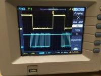
I managed to dig up the source code for a PET video generator I made out of an Atmel ATTiny2313. The source says I wrote it in 2017. I found a chip, flashed it, and put it on the Oscilliscope:

IMG_8656.JPG
This is the H-drive signal and video data signal.


IMG_8657.JPG
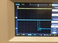
And the V-drive signal and video data.

So now I guess I have to drag this all downstairs and connect it to the PET and see what the test pattern looks like.
 
I managed to dig up the source code for a PET video generator I made out of an Atmel ATTiny2313. The source says I wrote it in 2017. I found a chip, flashed it, and put it on the Oscilliscope:

View attachment 1258246
This is the H-drive signal and video data signal.


View attachment 1258247
And the V-drive signal and video data.

So now I guess I have to drag this all downstairs and connect it to the PET and see what the test pattern looks like.
that looks like the HDrive pulse for the 12 inch vdu and crtc PET,which is an inverted wave compared to the non crtc PET.I'll check that later.
...if it is just inverted though,it would have the wrong timing with respect to the video dsta to suit the non crtc pet, but that could easily be modified in your firmware.
 
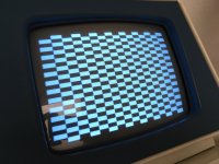
IMG_8665.JPG

It works! (Sorry for the glare, the monitor is tilted up towards a sky-light.)

I'll put up the source code if anybody is interested. The way it works, the Atmel AVR's have some versatile timers so I programmed one to create the H-drive signal with the correct frequency and duty cycle. I also programmed it to interrupt the CPU every rising edge of H-drive. The interrupt handler counts lines and either toggles the V-drive signal, "bit-bangs" the video data, or does nothing.

that looks like the HDrive pulse for the 12 inch vdu and crtc PET,which is an inverted wave compared to the non crtc PET.I'll check that later.
...if it is just inverted though,it would have the wrong timing with respect to the video dsta to suit the non crtc pet, but that could easily be modified in your firmware.
I'm pretty sure it's correct: the H-drive signal is high for 24 (us) clocks, low for 40 clocks.
 
I'll put up the source code if anybody is interested. The way it works, the Atmel AVR's have some versatile timers so I programmed one to create the H-drive signal with the correct frequency and duty cycle. I also programmed it to interrupt the CPU every rising edge of H-drive. The interrupt handler counts lines and either toggles the V-drive signal, "bit-bangs" the video data, or does nothing.

FWIW, if you want to get rid of the “sawtooth” on the vertical lines a trick you can use is sleep the CPU before the horizontal interrupt fires on every line. (This is standard fare in atmel Arduino video generators.) Otherwise there’s unpredictable latency in responding to the interrupt.
 
View attachment 1258252


I'm pretty sure it's correct: the H-drive signal is high for 24 (us) clocks, low for 40 clocks.
Yes it was around the other way sorry I had to look it up, your signal suits the 9" pet not the 12" pet The H drive signal for the 12" PET is inverted compared to your one, and a higher frequency too. It would be good to have a generator that could do both PETs.

Your test pattern is good for showing the stretched horizontal linearity on the left side of the scan, typical of the 9" version of the PET VDU without the linearity coil.
 
FWIW, if you want to get rid of the “sawtooth” on the vertical lines a trick you can use is sleep the CPU before the horizontal interrupt fires on every line. (This is standard fare in atmel Arduino video generators.) Otherwise there’s unpredictable latency in responding to the interrupt.
Thanks for the suggestion! Looks like there is a one clock (50ns) jitter between H-drive and the beginning of video data:

IMG_8669.JPG

I inserted a sleep instruction and it made it worse and the test pattern started "shimmering." But, it turns out you have to enable the sleep instruction by setting a bit in the MCUCR. Now it seems more solid:

IMG_8670.JPG
 
Cool. Yeah, it can be fun to tune these things. The wall I was beating my head against a few months ago was getting my 324-as-a-CRTC code to give me interlaced output. After hitting it with a shoe enough times it works pretty well and reliably on both real CRTs and digital TVs/HDMI converters, although there's still some black magic in the latter.

interlaced_sml.jpg
 
I'll put up the source code if anybody is interested. The way it works, the Atmel AVR's have some versatile timers so I programmed one to create the H-drive signal with the correct frequency and duty cycle. I also programmed it to interrupt the CPU every rising edge of H-drive. The interrupt handler counts lines and either toggles the V-drive signal, "bit-bangs" the video data, or does nothing.
This is brilliant! I just knew people would've figured this out before. :)
If you can share the source code, or DM it to me, it'll be great. Will clearly share with everyone on any changes. I definitely intent to support both non-CRTC and CRTC circuits.
 
Also another thing your test pattern shows up nicely is the slightly compressed horizontal linearity near the center with respect to the sides. This is because the 10uF S correction capacitor in this vdu is a little high. That problem is solved by fitting an 8uF or 8.2uF poly cap.

The left sided stretched linearity is vastly improved by adding an additional interesting germanium energy recovery diode in parallel with the one that is there. The CRT focus can also be improved especially for the Green CRT's,, it looks pretty good for your CRT, except for the corners. The details are in this article:

 
Last edited:
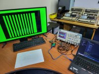
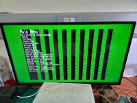
Got the timing mostly sorted now for the 9" monitor. Using an Arduino for now. The lack of fine control over timing necessitated the last, fatter bar. But it's 100% for what I wanted, a simple signal to feed a PET monitor to help with repair. Will likely switch to a faster CPU later to do more intricate patterns.

Tested it on an actual 9" and it looked good.

9-inch.jpg
 
Back
Top