Upcoming Events:
| VCF West | Aug 01 - 02 2025, | CHM, Mountain View, CA |
| VCF Midwest | Sep 13 - 14 2025, | Schaumburg, IL |
| VCF Montreal | Jan 24 - 25, 2026, | RMC Saint Jean, Montreal, Canada |
| VCF SoCal | Feb 14 - 15, 2026, | Hotel Fera, Orange CA |
| VCF Southwest | May 29 - 31, 2026, | Westin Dallas Fort Worth Airport |
| VCF Southeast | June, 2026 | Atlanta, GA |
-
Please review our updated Terms and Rules here
You are using an out of date browser. It may not display this or other websites correctly.
You should upgrade or use an alternative browser.
You should upgrade or use an alternative browser.
PETunia's Repair Log
- Thread starter Nivag Swerdna
- Start date
Nivag Swerdna
Veteran Member

ROMS installed...
H7 EMPTY
H6 UVEPROM adapter installed upside down! Contains image slightly MODIFIED rom-1-d000.901439-02.bin and vanilla rom-1-d800.901439-06.bin. Should be in H2?
H5 MOS / MPS 6540 / 012 4278A -> OK
H4 MOS / MPS 6540 / 016 4278A -> OK
H3 MOS / MPS 6540 / 015 4378A -> OK
H2 MOS / MPS 6540 / 018 4478A -> OK but should be in H7????
H1 MOS / MPS 6540 / 019 4178A -> OK
I removed them all and read the contents.
MOS / MPS 6540 / 012 4278A from H5 runs very hot and returns only 00s and 08s... -> DEAD
I'm slightly concerned about the $D000-$D7FF region of MODIFIED rom-1-d000.901439-02.bin
I think if I make a replacement for H5 which is MOS / MPS 6540 / 012 4278A aka rom-1-c800.901439-05.bin, put the MOS / MPS 6540 / 018 4478A from H2 into H7 and put the UVEPROM adapter the other way up into H2...
... need to create an H5.
dave_m
Veteran Member
My reading of the schematic indicates the following:
C000 H1 901439-13
C800 H5 901439-14
D000 H2 901439-15
D800 H6 901439-16
E000 H3 901439-17
F000 H4 901439-18
F800 H7 901439-19
Also check ROM images :http://www.zimmers.net/anonftp/pub/cbm/firmware/computers/pet/index.html. It's a little confusing for these 2K ROMs.
C000 H1 901439-13
C800 H5 901439-14
D000 H2 901439-15
D800 H6 901439-16
E000 H3 901439-17
F000 H4 901439-18
F800 H7 901439-19
Also check ROM images :http://www.zimmers.net/anonftp/pub/cbm/firmware/computers/pet/index.html. It's a little confusing for these 2K ROMs.
dave_m
Veteran Member
These should be the part numbers and dash numbers for the 6540 ROMs. The parts themselves may just have the dash number such as MPS 6540-013 the rest of the number is the manufacturing date.
You appear to have a mix of BASIC 1 and BASIC 2 ROMs (if I am seeing a -012. The photo is not clear). They may not play together. Note that Zimmer's calls BASIC 2 "BASIC 3". They call the Revised BASIC 1 "BASIC2". Very confusing.
You appear to have a mix of BASIC 1 and BASIC 2 ROMs (if I am seeing a -012. The photo is not clear). They may not play together. Note that Zimmer's calls BASIC 2 "BASIC 3". They call the Revised BASIC 1 "BASIC2". Very confusing.
Last edited:
dave_m
Veteran Member
If it turns out you have a bad mix of ROMs and/or have to replace a bunch of them, consider replacing all of them using The ROMulator. For your configuration (original 2001) you would set the dip switches to SW1 on, SW2 off, SW3 on, and SW4 off.
https://bitfixer.com/product/romulator/
In any case, good luck with the repair of your PET.
https://bitfixer.com/product/romulator/
In any case, good luck with the repair of your PET.
Nivag Swerdna
Veteran Member
I created a ROM replacement which I named a "Omni ROMulator" which I now realise clashes with the partial name of the product you replied with! Great minds think alike. I will rename my device at the next rev.
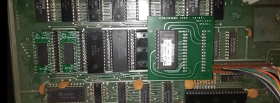
Anyway
I replaced $C000-$CFFF with a 4K Omni at H1 (also replaces H5) images rom-2-c000.901439-09.bin & rom-1-c800.901439-05.bin
and
replaced $D000-$DFFF with a 4K Omni at H2 (also replaces H6) images rom-1-d000.901439-02.bin & rom-1-d800.901439-06.bin
I am using the original MOS / MPS 6540 / 015 4378A at H3
and
the original MOS / MPS 6540 / 016 4278A at H4
I then burnt the https://github.com/vossi1/2001test tester into a 2716 and put it in the Skyles's adapter at H7.
I also replaced some bad 6550 with parts supplied by Little Diode
I get...
Nivag Swerdna
Veteran Member
Running the tester..
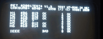
Now the Skyles adapter is really designed for 4K so I think there is bus contention for $F000 and that's why the checksum of H4 is wrong.
So... removing the Skyles adapter...
I put the MOS / MPS 6540 / 018 4478A which arrived in H2 in its correct location H7
I'm 80% sure I have a complete set of ROMs and good 6550s
And turned on...
I get garbage for a second and then the screen clears to Black
No idea what to do next!
Nivag Swerdna
Veteran Member
I created a proper tester ROM for H7 today and tested again...
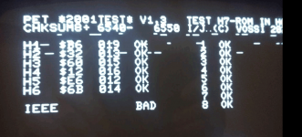
So I now have a complete and working set of H1 to H6
I also tested the original MOS / MPS 6540 / 018 4478A by putting it in H6 and get...
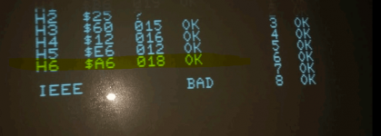
which I think proves that works and so my moving the MOS / MPS 6540 / 018 4478A into H7 and using the other ROM/Replacements tested above that should give me a complete set.
So now it boots to a black screen!
One thing I did notice is that the tester ROM doesn't always give the same results... mostly it does but sometimes I get differing answers... maybe that is a clue.
PS
Apologies for the lag in these posts... I am a new member and all my replies have to be moderated.

So I now have a complete and working set of H1 to H6
I also tested the original MOS / MPS 6540 / 018 4478A by putting it in H6 and get...

which I think proves that works and so my moving the MOS / MPS 6540 / 018 4478A into H7 and using the other ROM/Replacements tested above that should give me a complete set.
So now it boots to a black screen!
One thing I did notice is that the tester ROM doesn't always give the same results... mostly it does but sometimes I get differing answers... maybe that is a clue.
PS
Apologies for the lag in these posts... I am a new member and all my replies have to be moderated.
Nivag Swerdna
Veteran Member
So this is what I currently have...
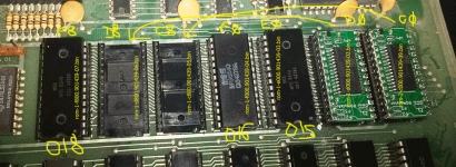
Is it OK to have rom-2-c000.901439-09.bin in H1? I believe that is that the parts list at http://www.zimmers.net/anonftp/pub/cbm/schematics/computers/pet/2001/2001_main_logic_assembly.pdf is implying... i.e. 6540-019 ROM at H1 which is 901439-09 ?

Is it OK to have rom-2-c000.901439-09.bin in H1? I believe that is that the parts list at http://www.zimmers.net/anonftp/pub/cbm/schematics/computers/pet/2001/2001_main_logic_assembly.pdf is implying... i.e. 6540-019 ROM at H1 which is 901439-09 ?
Nivag Swerdna
Veteran Member
So now it boots... first garbage and then the screen clears. I think I have good ROMs and OK RAM...
Is there a way to test the PIAs and VIA? What should I expect if I boot with these removed?
Is there a way to test the PIAs and VIA? What should I expect if I boot with these removed?
dave_m
Veteran Member
I think the set you have in your PET now is the BASIC 1 Revised (what zimmer calls BASIC 2). I did not realize the dash numbers on the 6540 ROMs do not match the 901439 dash numbers! My message # 4 is in error!!
Garbage and then blank screen usually means the PET is starting to boot, clears RAM but then gets quickly lost. Yes you can remove PIAs and VIA and it should show the PET initial screen, and then system stops. If this happens one of the three big chips is bad.
Garbage and then blank screen usually means the PET is starting to boot, clears RAM but then gets quickly lost. Yes you can remove PIAs and VIA and it should show the PET initial screen, and then system stops. If this happens one of the three big chips is bad.
Last edited:
Nivag Swerdna
Veteran Member
Thanks. I have removed the PIAs... no change... will remove VIA next.
One thing I noticed is the 6550s are noticeably warm to the touch. Since this is my first PET I don't know if that is normal or not?
One thing I noticed is the 6550s are noticeably warm to the touch. Since this is my first PET I don't know if that is normal or not?
Nivag Swerdna
Veteran Member
Zimmer BASIC 2 that's what I was aiming for. (I assumed that was BASIC 2!)
I thought I should measure voltages as I had rather naively trusted the seller who said they had checked regulation... Measuring betweeb Pin 1 (VSS) and Pin 27 (CS2=VDD) on the ROMs I get 5.09 V on DC range... but on AC range... I get an alternating value between and several mV and 2V... looks like I will need to get the board out and measure all the regulators?
I thought I should measure voltages as I had rather naively trusted the seller who said they had checked regulation... Measuring betweeb Pin 1 (VSS) and Pin 27 (CS2=VDD) on the ROMs I get 5.09 V on DC range... but on AC range... I get an alternating value between and several mV and 2V... looks like I will need to get the board out and measure all the regulators?
dave_m
Veteran Member
Eventually you may want the real BASIC 2 (zimmer BASIC3) as it fixes the IEEE port and allows for floppy drives or emulated PET Drives so you can easily load programs.
All the old NMOS parts like 6540 and 6550 run hot.
At the back of the mainboard, there is a screw that connects the board to chassis ground. If you are attaching the voltmeter return (black wire) to the chassis, make sure that spot is unpainted.
If there is no boot screen when the PIAs and VIA are removed, and you think the ROM and RAM are good (due to PET diagnostics program), then there may be an issue with the address or data bus. There are simple tools you can make to test the buses.
Nivag Swerdna
Veteran Member
(I seem to be unable to edit my earlier post #13; probably my newbie status... anyway I think the voltages are OK and I must have been reading a data pin)
I scoped the Voltage Regulator outputs... some wobble but probably OK enough...
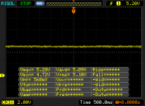
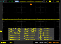
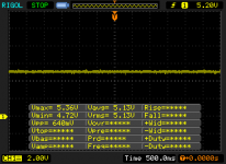
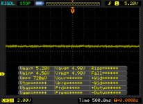
I also swapped the PIAs... no difference... boot to garbage... pause... black...
I scoped the Voltage Regulator outputs... some wobble but probably OK enough...


I also swapped the PIAs... no difference... boot to garbage... pause... black...
VERAULT
Veteran Member
- Joined
- Jan 30, 2012
- Messages
- 9,999
Hi,
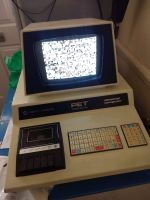
I'm new to this forum (although not new to computers) and have recently purchased a not working Commodore PET 2001 which I hope to repair...
View attachment 62031
I have video which is good and characters are nicely formed so that is good
I am working through the ROMs (these are 6540s)
Nice original PET, just curious how much did you pay for it? (curious what the UK prices are on something like this).
daver2
10k Member
Usual things after the power supply are:
Do you have a clock on the CPU pin 39? You should see a 1 MHz clock.
Is the CPU in a permanent reset - check CPU pin 40. Pin should be HIGH. However, on power-up, it should be LOW for a period of time then go HIGH.
Is the CPU in a permanent interrupt - check CPU pins 4 and 6. Both signals should either be HIGH or pulsing LOW. Never permanently LOW.
Is the CPU still executing instructions - check CPU pin 7. This line (SYNC) should pulse high for every instruction that is executed.
If these signals look OK - you have two ways to go next:
1. Make a NOP generator. This will allow you to test the address bus and address decoding logic in combination with your oscilloscope.
2. Download and burn my PETTESTER code into an EPROM and swap it for the EDIT ROM. This requires a bare minimum of hardware (e.g. an operational CPU and video logic) to operate. You have what appears to be an operational video sub-system and (with the tests above) we should be able to demonstrate an operational CPU.
The most likely cause, however, of your problem is a page 0 or page 1 RAM fault. On startup, the kernel ROM enters the EDIT ROM via a subroutine call. This initialises the hardware and clears the screen. To get back to the kernel ROM from the EDIT ROM subroutine, the CPU performs a RETurn instruction. If page 1 RAM is non functional, the CPU doesn't return back to where it came from and that is the last real thing the CPU will do... My PETTESTER does not assume that the RAM is working - and will test it out before using it. It will also check that the ROMS are correct (by displaying the checksum).
I assume the CPU and EDIT ROM are in IC sockets?
Incidentally, you can't edit your posts any more after a period of time.
Dave
Last edited:
Nivag Swerdna
Veteran Member
Isn't that like asking a lady her age; I would never divulge. I did buy it on eBay earlier in the year... so you could search the sold listings.Nice original PET, just curious how much did you pay for it? (curious what the UK prices are on something like this).
dave_m
Veteran Member
Nivag Swerdna;630397 I scoped the Voltage Regulator outputs... some wobble but probably OK enough... [ATTACH=CONFIG said:62294[/ATTACH]
This is indicating .75V of noise. This seems way to much for TTL if it is real. Where was your scope return for these measurements?
A suggestion - burn daver2's diagnostic code and place in the $E000 address socket (H3). It has a better RAM test. It is located here: https://drive.google.com/drive/folders/1fyLbr1kcG98a2FDOMo1H5pj9lIdJpHcx?sort=13&direction=a
It requires the normal kernel ROM installed (H7).
Note that it will provide sum checks on 4K boundaries for the ROMs. Don't worry about that right now; just see if they are changing and that the RAM is OK.
Nivag Swerdna
Veteran Member
I have been using vossi tester https://github.com/vossi1/2001test ... seems to prove 6502 good, address decode good, reset (probably good),...
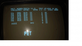
Although I have noticed that sometimes on power on it reports bad... (normally the first time after cold)... mostly it reports ROMs OK and RAMs OK (although I have gone for a divide and conquer approach so only I1/I2 and J1/J2 are currently populated).
I'll try a few of the above; thanks for your help.

