• Please review our updated Terms and Rules here

PiDP-8/I

Hi All;

Oscar, I am Wondering, If You would be willing to sell, Just the Front Panel Board ??
I would try and see if I could make it work on/with my PDP 8i clone..

THANK YOU Marty
 
Hi Oscar,

Absolutely think your doing an excellent job on this kit.

To marry one of the most classic vintage computer operational panels with such a state of the art micro as the Raspberry Pie is pure elegance and genius. Allows young foke to really get to appreciate the beginning days of computing, yet with a simple action have the ability to work with a state of the art development kit.

Akin to allowing a passenger of an Airbus A380 to ride in the observers seat of a Sopwith camel today.

Your electronics teacher should give you 1000 marks out of 100.

As an aside, I was reading your web page on assembly of the kit, and it struck me, that the 26 switches on your 8i panel, appear all to have the same operational mode. (Mind you maybe I am missing something)

But it made me wonder and go and look at my original DEC 8i front panel.

674.jpg

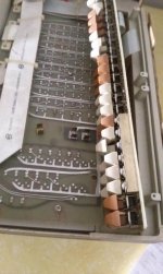
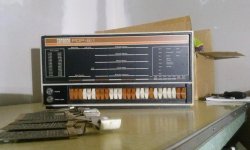
Close inspection shows that 6 of the switches on my genuine 8i have a spring bar installed behind the switch. That's the solid block of steel in pic

668.jpg

This make these 6 switches only momentary. Once you let go, they spring back to the original position. The steel bar has 6 separate leafs of spring steel the go between it and each switch.

5 of the switches (start, load add, exam, con, stop) have their 'Off' position as up, and one ( dep) has its 'Off' position down.

I am curious why yours all seem to be 2 position toggle operation.

Guessing that the software emulator takes care somewhat ?

Look forward heaps to get my kit and assemble it.

best regards
David
 
David,

Thanks for the kind words! :)

As an aside, I was reading your web page on assembly of the kit, and it struck me, that the 26 switches on your 8i panel, appear all to have the same operational mode. (Mind you maybe I am missing something)

No - you're not missing anything. Unless you make a modification (see below) the momentary switches of the original are replaced with just normal toggle switches on the PiDP. Meaning you have to flip them back up manually. The momentary signal is created by software the moment you toggle down (for instance) the STOP switch; how long it remains depressed then does not matter.

Many people put springs taken out of ballpoint pens or BIC cigarette lighters into the hollow switch cap. That makes the switches momentary... it's a very simple hack and works well. But in daily use, having to toggle the STOP switch down/up is not really that problematic. So most seem to leave it like it is.

There's one other Cardinal Sin in the PiDP: the DEP switch is placed 'upside down' on the real 8/I. I chose not to do that - although it takes one line of code to make it behave like in the original.

Kind regards,

Oscar.
 
Gents,

I am precisely at the step in assembly where I could put in the little springs. The switches are all painted and aligned on the skewer, but not yet soldered. I think I would like to add the springs. Could you tell me precisely which are momentary on the real 8/i and their position relative to the right end? Also, are they momentary on the down press, or up press? (on my 8/e, deposit is momentary on the up press.) If there is a link to a discussion of the little spring modification, that might be good to paste here as well. (Admittedly, I did not search for it yet.)

Thanks,
Lou

PS. Next's switch painting method worked fantastic. I found and used the same paint he did. I also painted the white switches.
 
Gents,

I am precisely at the step in assembly where I could put in the little springs. The switches are all painted and aligned on the skewer, but not yet soldered. I think I would like to add the springs. Could you tell me precisely which are momentary on the real 8/i and their position relative to the right end? Also, are they momentary on the down press, or up press?


Hi Lou,

Just went and looked at my 8i and took the attached photo. Hope it at the following description helps.

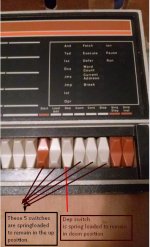
5 of the switches (start, load add, exam, con, stop) have their 'Off' position as up, and one ( dep) has its 'Off' position down.

8i front panel spring switches.jpg

6th switch in from right hand end is spring loaded to remain/ return to the down position when released. thats the Dep switch

3rd, 4th, 5th, 7th and 8th from right hand end are spring loaded to remain/ return to the up position when released.
 
Hi Lou,

6th switch in from right hand end is spring loaded to remain/ return to the down position when released. thats the Dep switch

3rd, 4th, 5th, 7th and 8th from right hand end are spring loaded to remain/ return to the up position when released.

I was not sure my initial Australian Kangaroo type wording, was as clear per your question after I posted it, so I expanded it to answer per your question.

6th switch in from right hand end is spring loaded to remain/ return to the down position when released. thats the Dep switch. It is momentary on the UP press.

3rd, 4th, 5th, 7th and 8th from right hand end are spring loaded to remain/ return to the up position when released ie are momentary on the DOWN press

felt it better to really be clear in the wording as unsoldering or removing caps one installed is a real pain.

As an aside I am debating removing one of my "brown" switch levers and going to a Masters Home Improvements store, and seeing what their paint, matching system will come up with as a color.

Mind you I am nervous of removing one in case I damage it.

regards
David
 
Hi All;

Inotarobot, "" As an aside I am debating removing one of my "brown" switch levers and going to a Masters Home Improvements store, and seeing what their paint, matching system will come up with as a color. ""
"" Mind you I am nervous of removing one in case I damage it. ""
Instead of removing one Switch cover, just bring the whole thing down..

THANK YOU Marty
 
Hi Marty,

Quote "Instead of removing one Switch cover, just bring the whole thing down.." Quote.

I did consider that Marty, however the cables that go between the front panel and Processor already have some damage,so was more nervous of them being flexed un-necessarily, compared to maybe damaging one switch cover. In either case, there are risks. But I will heed your advice and take panel and if there is to much risk of damage to the panel and cables, then I will remove a switch lever while I am at the store.

Thanks for you thoughts
regards
David
 
Hi All;

Inotarobot, "" I did consider that Marty, however the cables that go between the front panel and Processor already have some damage,so was more nervous of them being flexed un-necessarily, compared to maybe damaging one switch cover. ""
In that case bring the whole computer down, I am sure it would create quite a stir in the paint department..
And then while Your at it, take it over to one of these places that "Says" they will repair Your PC.. I always get a laugh taking an Old computer to them, especially if they say they will repair any PC..
I took an Altair to them. Not that I would actually let them touch it, repair wise.. But, their response is always Great..

THANK YOU Marty
 
Hi All;

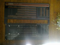
Oscar, THANK YOU !!! I got the Board and the FacePlate and the misc Parts..
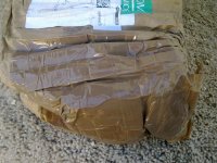
The Outside of the Package was quite Damaged, but what was inside was fine..


002.jpg 003.jpg 004.jpg

THANK YOU Marty
 
Last edited:
Two real RS232 Serial Ports?

Two real RS232 Serial Ports?

Folks,

I made a little more progress on my PiDP-8/i over the holiday. I now have the momentary switches fitted with return springs (cheapo retractable pen springs, cut down) and the deposit key oriented properly (opposite the other momentaries), and all back on the skewer. I also got out the B+ I had bought a while back and made the SD card with the latest distribution. My mind is moving on though to how I want to actually use this.

I am old school and want a real RS232 TTY console interface (03/04). That appears to be not hard with a board mod to my V1.0 board and a MAX232. However, I want a second serial interface (40/41) for connecting a serial printer (likely my LA36). How can I get that second serial port? Can an FTDI usb to serial adapter be plugged into a Pi USB port (and then a MAX232 to that)? Will the Pi understand what to do with the FTDI adapter? Is there a configuration file to tell SimH to direct 40/41 to a particular USB port? Sorry so many questions, this is my first real work with an emulator or SimH (I usually just run the real iron!)

Thanks,
Lou
 
Folks,

I am old school and want a real RS232 TTY console interface (03/04). That appears to be not hard with a board mod to my V1.0 board and a MAX232. However, I want a second serial interface (40/41) for connecting a serial printer (likely my LA36). How can I get that second serial port? Can an FTDI usb to serial adapter be plugged into a Pi USB port (and then a MAX232 to that)? Will the Pi understand what to do with the FTDI adapter? Is there a configuration file to tell SimH to direct 40/41 to a particular USB port? Sorry so many questions, this is my first real work with an emulator or SimH (I usually just run the real iron!)

Thanks,
Lou

Hi Lou,

well one way to get RS232 on the Pi is to use a plug-ON board that has the right hardware already. for us$11 they are available ex China with free shipping.

http://www.ebay.com.au/itm/RS232-GP...615437?hash=item51becf6b4d:g:JrMAAOSw8lBTo~YH
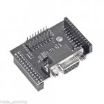
pi rs232 plugon..JPG

Feature

The UART is /dev/ttyAMAO, it defaults to output system log. But if user wants to use this UART to connect to other modules through UART, for example, GPS module, we need to change the configuration.
The detailed steps are as following:
We need to modify two files: /boot/cmdline.txt and /etc/inittab.
Modify /boot/cmdline.txt:
Replace the original content:
dwc_otg.lpm_enable=0 console=ttyAMA0,115200 kgdboc=ttyAMA0,115200 console=tty1 root=/dev/mmcblk0p2 rootfstype=ext4 elevator=deadline rootwait
With:
dwc_otg.lpm_enable=0 console=tty1 root=/dev/mmcblk0p2 rootfstype=ext4 elevator=deadline rootwait

Modify /etc/inittab:
Comment out the last line of /etc/inittab. To comment out, it simply addess a '#'.
$ sudo vi /etc/inittab
T0:23:respawn:/sbin/getty -L ttyAMA0 115200 vt100
Save the changes, and reboot. We will get an UART with baud rate of 115200.


or another more versatile option appears at first glance to be this Rs232 board for us$17 from Asia + about us$5 for shipping


http://www.ebay.com.au/itm/ADD-ON-B...770469?hash=item3f53f90d65:g:whwAAOSwEetV~tuR

RS232 GPIO UART Module For Raspberry Pi
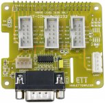
pi rs232 plugon opt 2.jpg

Board ET-CONV10/RS232 HAT is specifically designed for use with 40PIN of Board RASPBERRY PI. There are 2 types of application as follows;

1. It is used as RS232 PORT.
2. It changes Connector 40PIN of RASPBERRY to Connector 10PIN ETT Standard; so, it can be used with I/O Boards of ETT conveniently.
User Manual (English Version) => http://www.mediafire.com/view/9mbx1cjj5hyejk7/Manual_of_ET-CONV10_RS232_HAT.pdf
 
Last edited:
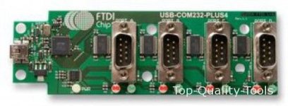
I like the specs of the GearMo 4-port item that HoJoPo recommended - lowest baud rate is 300 so not a solution for teletype but pretty good for most other peripherals. It should also be a clean installation in the PiDP8 chassis. I haven't used one - here's hoping it is Lou's choice and it works!

Jack
 
Deposit switch inversion

Deposit switch inversion

Folks,

So I finally assembled the kit this weekend. I've got the serial console working at 9600 baud in old school fashion, having done the serial mod, using a MAX232, and compiling the code as directed for the serial mod. I also used the pen spring method to make the correct switches momentary. I also put the spring on the side of the deposit switch to mimic the deposit switch action on the real 8/I. Unfortuately that is not the way the stock pidp-8/i release was set up to handle the deposit switch.

I had read elsewhere that the gpio.c file could be modified to invert the action of the deposit switch. Maybe it is obvious to C programmers exactly how and where to make the modification, but it was not obvious to me. I have looked around, but I can't find explicitly where and how to patch the gpio.c file. Has anyone here done this mod and can point me in the right direction?

Thanks,
Lou
 
Back
Top