• Please review our updated Terms and Rules here

Powertran Cortex Issues

Well, good news; after some significant help from Stuart last night, and overcoming a schoolboy error on my part, I now have a working disk system. There were several problems though. The first was power; whilst being powered from the Cortex PSU the disk activity failed. Change to the disk system stand-alone power supply and it worked, but only Reading from the disk. The difference in power supplies is minimal, Cortex PSU 11.6v and 5.2v, Disk PSU 11.8v and 5.0v, but obviously enough to make a difference. I'll be diving deeper into the Cortex PSU power distribution soon to determine why. But as I said further investigation revealed that this only got the disk Reading working, Writing/Formatting was still not working. It further transpired that IC63, (IC6 on my motherboard), an SN74LS07 Hex Buffer/Driver, was showing the WRITE GATE signal on the actual Pin 2 of IC63, but it wasn't making it onto the motherboard via the socket!! Some judicious pin bending on the IC gave the required pressure to give a good contact and hey presto Writing/Formatting. It highlights the variability of the reliability of cheap flat/stamped sockets over the more expensive turned pin, phosphor-bronze insert type. I'll be replacing the socket with said turned pin type as soon as possible.
It just re-enforces the "fresh pair of eyes" situation can be so helpful when you are stuck. Familiarity with the CDOS syntax, as well as having another, working, Cortex and disks to swap with was also invaluable. Many thanks to Stuart!!!! :biggrin:

Besides making a DISKCOPY of the CDOS disk, I've now managed to create two working CDOS floppy disks from scratch using the prescribed method and PC CommsUtil; would you like one? Happy to post one.

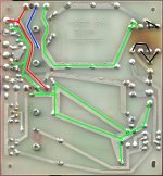
Looking at your symptoms above, have you checked that the various signals to/from the Floppy Drive are visible on the 9909 IC and the various buffer chips IC83, 84 and 85 to/from the Floppy Drive? I've attached the schematic that covers the circuitry involved.
 

Attachments

That's great! I had so many issues related to the sockets I chose to re-socket the whole motherboard. I also tested all the chips I could before replacing them. So I know any of the standard chips at least test ok. I did beep out most of the chips when they were back in, but I've definitely not done 100%
I guess the best use of time is to be sure everything is able to get to where it's supposed to. At least that way I can tick one thing off the list of potential issues.
I wouldn't say no to a known good boot disk! as long as it's single sided, the previous owner cheaped out on the drives ;)
I guess now you have a working system you need to get a gotek so we can test configs. I did check over the settings I had and can't see anything out (my example a few post up does have the wrong speed ... 500 rather than 250 as I was busy testing loads of different options to see if any made a difference and copied in the wrong one) there's some things we could add like emulating spin up/down speeds and such, but I'd start without them.
 
Happy to send a disk. Can you DM me and I can let you know contact details for address, etc. please? I'm still on the Newbie Probation list so can't send DM's. :( I can apparently reply to them though. :)
I'll work on adding a GoTek as one of my drives is ploughing oxide and I don't know if I can fix it yet. A Gotek would seem to be a sensible option, so that I'd have one of each technology.
 
If a duff disk sheds oxide onto the head then it will get stuck there and then damage any more disks you put in the drive.
You need to give the heads a really good clean if you get a disk like that.
 
If a duff disk sheds oxide onto the head then it will get stuck there and then damage any more disks you put in the drive.
You need to give the heads a really good clean if you get a disk like that.
I've already given the offending drive head a good clean twice. Obviously I'm loathe to try a new disk in it as they're at a premium, but at some point I will have to. I'm going to find a way to have a really close look at the head before I do that though.
 
I've used those as well as cotton buds but sometimes the is so much oxide on the head i had to resort to scraping it off carefully with the edge of a scalpel.
The heads are ceramic which should be harder than the scalpel blade.
I would only try this on the heads that are completely smooth and as a last resort but my drives survived doing this a couple of times while i was trying to archive a pile of disks.
Also look at the disk surface first, if there are any random patterns on the surface it's mould which won't do your heads much good either, it's surprisingly hard.
 
"chamois-tipped swaps" ? I've seen a few things in my time but not these. Worth a try, thanks.
"scraping it off carefully with the edge of a scalpel" :eek::eek::eek::eek::eek::eek::eek::eek: I realise that ceramic is as hard as nails (harder in fact) but.... I will give it a try if all else fails. Thanks. (it's like raking my nails down a blackboard - you know it's not doing any real harm but goes against your base insticts!).
The (only) disk that I've tried in the drive looked perfect before it was tried in the drive, and in fact it worked 3 or 4 times without issue at first. After the drive had scratched the disk, I cleaned the heads, and the disk whole surface, which still looked perfect except for the scratch. After trying the disk again, and had it scratched further, I further cleaned the head, and split the disk jacket welds to extract the disk. The rest of the disk (both sides) still looked perfect and the jacket interior was spotless too. No signs of mould, oxide shedding or other contamination at all. At this time I can't find any evidence of the disk being at fault, hence my suspicion of the drive head.
 
Well I finally got the drive head clean. It didn't come to scalpels and scraping but it was close. I dismounted the head assembly so that I could get a magnified direct view of it and could see a line of black material across it. It was strangely regular, a long narrow oblong. I applied plenty of Isopropyl alcohol and used about half a dozen cotton buds with plenty of pressure, and it slowly came off. It would have been really difficult to do if the head was still in situ. Having restored the surface to a uniform shiny state, my next worry was getting the head alignment correct, however I seem to have got it right first time. I formatted a disk in the drive and copied files from the other drive, then swapped disks and read from both directories at different intervals without any difficluties or retries at all. I typed in Bill Harris' Disk Inspect program from the UG Newsletter 13.6, saving partial entries to both drives as I went. It gave me a nice view of the disk sectors. I'm still using the drives on their stand-alone power supply. I chwecked the disk surface at the end of the work and it was perfect.
My next move is to investigate the Cortex PSU and distribution to make the power distribution more regular across the system.

Many thanks to Jim and Stuart for all your sound advice, very much appreciated!!!
 
I got my cortex back on the bench over the weekend, but didn't get much time to look into the issues. Regarding the boot disk ... I was holding off a second as I wasn't sure if I had an issue or not. The drives that were fitted to the cortex are Canon MDD-110 which I can find very little about, so I'm just going on its twin headed brother the MDD-210. I got a bit sidetracked by the specification stating 80 tracks and 500KB max - so 40 tracks and 250KB in my case, which is smaller than expected ...... but, it may be that this was constructed before the standards were out for larger format disks and that they will work fine. I did a quick test with a greaseweazle and seemingly wrote (and could read and verify) one of the 320KB cortex disk images on my PC. So that suggests the drive is mostly if not completely functional.....
I got as far as starting to probe the inputs on IC84 starting with the data pin 30 output from the floppy, and was getting a lower than expected 3.4v even when inactive (it does pull to 0 successfully when sending data).... having said that the Canon manual does state "Logic 1 = 2.4 - 5.25v (inactive)" so in theory 3.4v is within spec, just seemed low if all it should have at that point is a pull up to 5v (I have checked the terminator resistors are in place on the floppy). The schematic for the Cortex also shows a 150 ohm R71 connected at this point ... but I had to stop "playing" before I found it, if I even have one on my revision.
So that's where I'm up to. Hopefully I'll get some more time in the next day or two to check the rest of the routing and check voltages.
 
Sounds as though you are on the right track, and not far off fixing the issue. R71 is part of the resistor pack located between ICs 82 and 85 adjacent the 8" ribbon connector and should be fitted. Do you get a solid +5v with the drive cable disconnected? Good luck.
 
I got my cortex back on the bench over the weekend, but didn't get much time to look into the issues. Regarding the boot disk ... I was holding off a second as I wasn't sure if I had an issue or not. The drives that were fitted to the cortex are Canon MDD-110 which I can find very little about, so I'm just going on its twin headed brother the MDD-210. I got a bit sidetracked by the specification stating 80 tracks and 500KB max - so 40 tracks and 250KB in my case, which is smaller than expected ...... but, it may be that this was constructed before the standards were out for larger format disks and that they will work fine. I did a quick test with a greaseweazle and seemingly wrote (and could read and verify) one of the 320KB cortex disk images on my PC. So that suggests the drive is mostly if not completely functional.....
I got as far as starting to probe the inputs on IC84 starting with the data pin 30 output from the floppy, and was getting a lower than expected 3.4v even when inactive (it does pull to 0 successfully when sending data).... having said that the Canon manual does state "Logic 1 = 2.4 - 5.25v (inactive)" so in theory 3.4v is within spec, just seemed low if all it should have at that point is a pull up to 5v (I have checked the terminator resistors are in place on the floppy). The schematic for the Cortex also shows a 150 ohm R71 connected at this point ... but I had to stop "playing" before I found it, if I even have one on my revision.
So that's where I'm up to. Hopefully I'll get some more time in the next day or two to check the rest of the routing and check voltages.

It's not the manual you are looking for but it does show your drive models capabilities, if that's any use? It mentions that the MDD-110 is only a 40 track single head drive. I don't know how the "Recovery Utils 80SSSD.dsk" file will fit on it?
 

Attachments

Last edited:
I got my cortex back on the bench over the weekend, but didn't get much time to look into the issues. Regarding the boot disk ... I was holding off a second as I wasn't sure if I had an issue or not. The drives that were fitted to the cortex are Canon MDD-110 which I can find very little about, so I'm just going on its twin headed brother the MDD-210. I got a bit sidetracked by the specification stating 80 tracks and 500KB max - so 40 tracks and 250KB in my case, which is smaller than expected ...... but, it may be that this was constructed before the standards were out for larger format disks and that they will work fine. I did a quick test with a greaseweazle and seemingly wrote (and could read and verify) one of the 320KB cortex disk images on my PC. So that suggests the drive is mostly if not completely functional.....
I got as far as starting to probe the inputs on IC84 starting with the data pin 30 output from the floppy, and was getting a lower than expected 3.4v even when inactive (it does pull to 0 successfully when sending data).... having said that the Canon manual does state "Logic 1 = 2.4 - 5.25v (inactive)" so in theory 3.4v is within spec, just seemed low if all it should have at that point is a pull up to 5v (I have checked the terminator resistors are in place on the floppy). The schematic for the Cortex also shows a 150 ohm R71 connected at this point ... but I had to stop "playing" before I found it, if I even have one on my revision.
So that's where I'm up to. Hopefully I'll get some more time in the next day or two to check the rest of the routing and check voltages.
I think your "500KB" and "250KB" are the transfer rates, not capacity. Capacities I believe are (from the Powertran website):

40T,SS,SD = 80K (40 tracks * 1 side * 16 sectors * 128 byte per sector)
40T,SS,DD = 160K (40 tracks * 1 side * 16 sectors * 256 byte per sector)
40T,DS,SD = 160K (40 tracks * 2 sides * 16 sectors * 128 byte per sector)
40T,DS,DD = 320K (40 tracks * 2 sides * 16 sectors * 256 byte per sector)

80T,SS,SD = 160K (80 tracks * 1 side * 16 sectors * 128 byte per sector)
80T,SS,DD = 320K (80 tracks * 1 side * 16 sectors * 256 byte per sector)
80T,DS,SD = 320K (80 tracks * 2 sides * 16 sectors * 128 byte per sector)
80T,DS,DD = 640K (80 tracks * 2 sides * 16 sectors * 256 byte per sector)
ahh yes.... which does mean that even if I get these drives working, they might be pretty useless at 160k.
Although having said that, i've just opened a couple of the disk images in hex and the 320k one I tested writing to only has about 3KB of data on it (which is why that looked fine when I read it back) and even one of the 640k ones only has 85KB on it, the rest is "00 00" or "D0 B5"
I would still expect them to format when selecting 40T,SS,DD though, or at least try to boot, but everything gives the same error......
I've done some poking and while no further towards identifying the issue, these are my findings.

1) I do not have a pull up resistor issue - the diagram shows read data (30) on pin 16 of IC84 .... it's not, it's pin 15 and that all looks good!
2) The pins depicted for the flipflops IC88 and IC69 are a bit off IC88a shows Q2,D2 and IC88b shows Q1 and Q2 so the link between D and Q should be D2 to Q1 so pin 12 to pin 5 (not 8). IC69 should also be pin 9 for Q2 not pin 5
3) The drive select pins seem to be backwards? so drive select 1 to 4 is shown as pins 6, 14, 12, 10 not 10, 12, 14, 6 but drive select does seem to select the correct drives with me, so I guess that's just an error on the numbering?
4) The diagram has "link to 32 on 5"" against floppy pin 14 for SIDE. I don't have that, so should probably put that in ... but the drives I have are single sided so I guess they wouldn't have used it.

Onward.......
 
I've just cured the voltage difference issue I mentioned earlier. I now have 0.01v difference between a chip on motherboard and a chip on the disk drive rather than 0.2 volt. I did this by beefing-up the pcb tracks on the rear of the Power Supply pcb by soldering on some decent wire. I think I seem to remember doing this when I built my original Cortex, but it was so long ago.
 
interesting. I've rebuilt the PSU and I'm not seeing any specific voltage issues, but something like that sounds worth doing anyway. Which specific tracks are you referring to?
I've made no real progress. everything I'm testing seems OK.
The only thing that's a bit odd is CE on the TMX9909 seems to be stuck high, but if it's enable low, how is it working.
trying to boot from the floppy or gotek and I can see data coming in on pin 30. I can see activity on A13-15 and D0-7 I can see the track 0 pulse coming in.
It's entirely possibly that I do have a faulty floppy drive somehow and the gotek doesn't work, but the greaseweazle suggests otherwise.
I ran a couple of wires along each pcb track for the +5v and Ground, and around the main 4 rectifier diodes, with plenty of solder. I used some silver plated annealed copper wire I had lying around, but really anything to improve current flow would do.
 

Attachments

  • Power Supply PCB 1a - Enhanced Tracks.jpg
    Power Supply PCB 1a - Enhanced Tracks.jpg
    7.5 MB · Views: 6
Just a thought; your MD110 drives are 40 Track, how have you created a CDOS Boot Disk? The instructions I have for creating a CDOS disk from scratch are all for 80 Track drives. Also re the CE signal; I think it would be a very quick/short duration pulse to program the 9909 to do it's job and then let it get on with it. It will transfer the data to the Memory using the DMA chip and then hand back to the CPU once done. It might be working, just too quick to see?
 
I've just found a utility called "System Config Utility 1v2" which gives some drives settings; Step = 10ms, Settle = 10ms, Load = 0ms. It's not much but it might help?
 
Back
Top