• Please review our updated Terms and Rules here

Programming 16L8 on NeedHam EMP-11 Programmer

Hi All;
Thank You, Chuck !!
I am going to try and do two things.. First, because of Your Help and Suggestions and Downloads, I will put into NotePad what I think is the origional file that might be the equations file, that You, Chuck talked/asked about earlier..
And see If by making a New file from scratch, might be the trick to make it work..
The other thing is to try and see where the Code is Hanging up, in the 003.. I have been trying to Remember by using my old Spectra Test Panel and Spectra 2A Test Panel.. But, things are not coming to mind and/or not working as I had hoped..

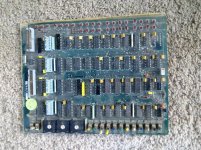
Here are some Pictures of the Test Panel and 2A Test Panel:
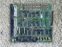
007.jpg 006.jpg

Here is the Equation file :

View attachment 16L8-DES.txt

THANK YOU Marty
 
Last edited:
You probably know this already and probably repeating myself (and others), but from my recollection, you would feed that Eq. through PALASM with a target of the original chip (if it's not already in the file) and then feed it through PAL2GAL if your programmer didn't have the conversion as an option . There was routine to minimise the logic, but I think that was part of PALASM. Worst case I could probably drag up the files if needed, they are around somewhere, but sounds like it's all in hand anyway. Likewise I could likely program if you can't get it sorted with your programmer.
 
Hi All;
SleepWalker, Thank You for Your Reply.. No, I haven't gotten it to work as of yet.. I think, I need to Copy the Page that is the OutLine of the Chip in "stars" and the Signal name and the pin numbers in it as well.. Then it may be happy, we'll see..

THANK YOU Marty
 
Here is the Equation file :

View attachment 21025

Marty,
Where did you get this source file? Did you transcribe it? There are typos in the /ONL equation where the input term SOLF is misspelled compared to the pin definition. It is also misspelled in the Function Table. When those were fixed to get it to ASSEMBLE correctly, the SIMULATION failed due to logic mismatch between the Function Table and the equations with the RWD and ONL outputs.

Here are the Errors:
Code:
5 - Simulate function table
0001 1X0100011N1H111LHLHN
0002 1X0000111N0H111LLLLN
0003 1X0000110N1H111LHLHN
0004 101000111N1H111LHHHN
0005 - L not found on pin 0016 - RWD
0005 110000101N1H111LHHHN
0006 - L not found on pin 0016 - RWD
0006 110000001N1L110LHLHN
0007 100010101N1H110HHLLN
0008 - H not found on pin 0016 - RWD
0008 100000101N1L101HHLLN
0009 100000111N1L101LHLHN
0010 - L not found on pin 0016 - RWD
0010 110000101N1L101LHLHN
0011 110000101N1L001HHLLN
0012 - H not found on pin 0016 - RWD
0012 000000101N1L101HHLLN
0013 000000111N1L101LHLLN
0014 - H not found on pin 0017 - ONL
0014 001111101N1L111LHLLN


Structured test verify error 


 Command : 0 - Display menu


DATA I/O CORP. - PALASM Design Adapter - 303A-100-V02  (C) 1982,1983


      - GENERAL COMMANDS -                    - I/O COMMANDS - 
0 - Display menu                          2 - Receive PALASM source 
1 - Enter family/pinout code              3 - Transmit PALASM source 
6 - Enter verify option                   B - Receive JEDEC data 
7 - Enter security fuse option            C - Transmit JEDEC data 
8 - Enter functional test data 
F - Configuration number 
G - Select attributes


    - SOURCE EQUATION COMMANDS -             - FUSE MAP COMMANDS - 
4 - Assemble PALASM source                A - Display fuse pattern 
5 - Simulate function table               D - Display fuse sumcheck 
9 - Edit source                           E - Edit fuse pattern 


NOTE - Always transmit an "ESC" before removing adapter 


 Command :
 
Hi All;
DaveM, Thank You for Your FeedBack..
"" Where did you get this source file? Did you transcribe it? "" YES !!
I would Love to know the ""How" and the "What"" of what You did , So I could do the same !!!!
I have no idea of how you did that..
Like I had said before, I have the file in PDF, but it is too Large to post here on the Forum.. If I could send it to some one who could, Just post the relevant pages, it would be easier for those of You checking my work..
See if this Helps --

View attachment 16L8-DES.txt

THANK YOU Marty
 
Last edited:

There are 14 Test Vectors listed in the source file (Function Table). When the Simulate Function Table command is performed, each Test Vector pattern is compared to the equations for correct logic. Currently Test Vectors #5,6,8,10 and 12 are incorrect for RWD output (pin 16), and Test Vector #14 is incorrect for the ONL output (pin 17).

For instance Test Vector #14 predicts that signal ONL should be a high with its input pattern, when by the equation, those input signals will produce a low. I'm assuming your transcription had typos. Did you have a brew or two before copying all of the source file? ;)

I'll have to check the file pdf to see if typos crept into these Test Vector patterns.

After programming, some PAL Programmer equipment such as Data I/O can use these Test Vectors to perform a Verify Function which will test the PAL outputs for correct patterns to ensure the device is fully functional.
-Dave
 
Last edited:
Marty, You can upload files to anonfiles.com, it just means that you (and whoever goes to get the file) gets another page open with some advertising rubbish on it. You save the link and then post it here. If you have Gmail and the like, they also have file storage, or for short-term transfer (up to 7 days for the free account) you can use filepigeon.com which has no ads, but the file will disappear after 7 days.

[edit - corrected typo in URL]
 
Hi All;
I got offers from two people to send the file to for the relevant pages.. And I have sent them a copy of the document..
SleepWalker, Thank You for Your suggestion.. I might just need to do that.. Also, on a side note, Do You SleepWalk ??
These files were origionally done on Data I/O programmers..
DaveM, "" Did you have a brew or two before copying all of the source file? "" No, I just tried to look accress the lines on the screen, it looks like I didn't do such a hot job.. Thanks for Your Help and suggestions..

THANK YOU Marty
 
Last edited:
There are 14 Test Vectors listed in the source file (Function Table). When the Simulate Function Table command is performed, each Test Vector pattern is compared to the equations for correct logic. Currently Test Vectors #5,6,8,10 and 12 are incorrect for RWD output (pin 16), and Test Vector #14 is incorrect for the ONL output (pin 17).

The RWD and ONL outputs feed back on themselves and the description says they are latching outputs. Does the simulation correctly handle latching outputs like these two outputs? I haven't looked at this closely to try to mentally simulate the behavior myself.
 
Hi All;
DaveM, Thank You for Posting the Necessary files..
FrankS, Thank You for Posting the Cupl files.. The JED files looks completely different than the one I had before..
Hopefully this will work..

THANK YOU Marty
 
The RWD and ONL outputs feed back on themselves and the description says they are latching outputs. Does the simulation correctly handle latching outputs like these two outputs? I haven't looked at this closely to try to mentally simulate the behavior myself.

Good point. The Simulator is the original FORTRAN PALASM. Maybe because of the feedback term, it has to know the previous State to work right? I'll look closer. But I have also found a discrepancy between the hand drawn schematic and the equations so things look dicey.
 
Hi All;
Tomorrow, when I try the file from FrankS, If that doesn't work then I can build the circuit and see if DaveM is correct..
"" But I have also found a discrepancy between the hand drawn schematic and the equations so things look dicey. ""
And I want to have a closer look at the Schematic, Of course, it could be that the schematic has an error, not knowing how all of it fits together, Since at present I don't have the full schematics..

THANK YOU Marty
 
Hi All;
Just when I said that I Didn't have the Schematics, Bruce Ray, Came thru with the Information, that I had Lost.. THANK YOU, Bruce !!
So, I NOW have Full Schematics..
I have two Versions, the Early pre-PAL Schematic and the Later Schematic with the PAL's..
DaveM, If You don't Mind I will Send them on to You, Page 6 of the Schematic with the PAL's is what is Relevant.. They will be two emails..

THANK YOU Marty
 
Last edited:
I have two Versions, the Early pre-PAL Schematic and the Later Schematic with the PAL's..

Here is the link to the pre-PAL schematic. I underlined in green the 5 outputs put into the new PAL.

Here is the link to the later schematic

How were the equations obtained for the PAL in the new schematic? Was a JEDEC file obtained from a working chip or was it 'reversed engineered' in some other way?
 
Hi All;
Thank You, DaveM, for posting this additional information..
"" How were the equations obtained for the PAL in the new schematic? Was a JEDEC file obtained from a working chip or was it 'reversed engineered' in some other way? ""
I don't know the answer, as all of this was done way before I was involved with Spectra Logic.. This was all Done in California, when Spectra Logic was there, I worked for the Company that Bought Spectra Logic, from its Parent company.. So, I was not around nor involved in any of the decisions.. Only one person came when the Company moved from California to Boulder, and He was not the designer of this unit..
My thought is that If You compare the single Sheet schematic, with the Pre-PAL schematic, that between the two was "How" the Equations were figured out for the later Schematic, to reduce its size by using Pals where ever they could to reduce its Printed Circuit board size.. I hope this makes sense..
There was an Earlier unit that was made that was called the "TapeWorm" it was the Tape part of this unit, before they added the Disk side of it.. I had not, nor have not ever seen any of those units.. The only units that I saw was the Three 'S03' Disk and Tape units.. I got one, and they were never used at the Boulder Spectra Logic site..
Tomorrow, I will try to redraw both Schematics and compare them and figure out the Equations from them as well.. Just to see if things match..

THANK YOU Marty
 
Last edited:
Last edited:
Back
Top