• Please review our updated Terms and Rules here

S100 hard disk controller

Roland Huisman

Veteran Member
Joined
Mar 24, 2011
Messages
1,526
Location
The Netherlands
It seems S100 ST506/412 compatible controllers are hard to find.
I was wondering, were there projects documented to use the standard
boards like the Xebec 1410 or Western Digital 1002 on the S100 bus?

The most intelligence is on those boards themself. So there must be a quite
simple way to hook up such a controller on the S100 bus. Of course you
need some boot ROM or a boot floppy which has the hard disk parameters for it.

I would love to have an old fashion hard disk in one of my S100 machines.
If there is a well documented DIY project from the old days I would
love to make my own board.

Regards, Roland
 
The only S-100 hard disk controller that I ever had any experience with was in the Heath/Zenith Z-100 systems. The Z-100 was a cross between a large motherboard system like the Kaypro and Osborne, and it also had the S-100 bus for additional memory and interface boards.

I currently have a Z-110 version, which was the computer, keyboard, and two floppy disk drives in one (very heavy) box. You have to add an external CRT for composite video display. The only S-100 board in it is the 256K RAM board.

Unfortunately, I do not have any docs on the hard disk controller, but, being it was from Heath, there should be documentation about it out on the Internet?

Good luck.

smp

UPDATE: Here are some links:

http://www.s100computers.com/Hardware Folder/HeathZenith/HDC/HDC.htm
http://www.s100computers.com/Hardware Folder/HeathZenith/Motherboard/Motherboard.htm
http://retrotechnology.com/herbs_stuff/z100.html
http://home.earthlink.net/~z100lifeline/data/IDE.html
http://home.earthlink.net/~z100lifeline/data/Z100Begin.html
 
Last edited:
For a time, I ran a WD1001 controller from the S100 bus. It's no big deal--basically a couple of latches and bus receivers. The controller is very simple to communicate with.
 
Yes, not exactly responsive to your request but ... you might find it interesting to look at the Vector Graphic Dual-Mode Floppy & Hard Disk Controller Board. There's one on eBay; search "s100 hard disk controller".

John Monahan has a schematic online:

http://www.s100computers.com/Hardware Folder/Vector Graphic/Dual FD-HD Controller/VG Dual HDC.htm

Manual (with a different schematic) here:

http://maben.homeip.net/static/S100/vector/cards/Vector Dual Mode Disk Controller.pdf

Some port information in the Technical Bulletin here:

http://www.pestingers.net/pdfs/s100-computers/vector-graphics/vector-misc-technical-bul.pdf
 
Last edited:
It is relatively simple to use an old XT 506 controller.
It just needs some latches and bus bus buffer.
I've adapted one to my NC4000 ( non-x86 ).
If you have a WD-1000 you can use a simple bus buffer.
You can look at the Olivetti M20 schematics on line for how
simple it is.
I made such a buffer for my M20 and used the controller from
a TRS80 5 Meg drive box ( essentially a WD-1000 ).
Again, a simple wire wrap project.
The XT board is the best to use since it has a sector buffer and
doesn't have any need for interrupts or special timing requirments.
Dwight
 
The only S-100 hard disk controller that I ever had any experience with was in the Heath/Zenith Z-100 systems.

Thanks for the links! I have that Z100 system too. Without hard disk,
but I have the original documentation for the hard disk controller.
I wonder how this controller would behave in an other S100 computer.

For a time, I ran a WD1001 controller from the S100 bus. It's no big deal--basically a couple of latches and bus receivers. The controller is very simple to communicate with.

Probably very simple yes. But you have to tell cp/m (or other OS) how to work with it as well...
I thought there must be some well documented hardware and software for it.
But maybe the info of the controller manual is enough to use it under CP/M.

Yes, not exactly responsive to your request but ... you might find it interesting to look at the Vector Graphic Dual-Mode Floppy & Hard Disk Controller Board.

Yes I've seen that one too... But the FDD part seems to be hard sectored.
And I've no idea how to make those floppy disks... I could not find software for it.
Otherwise I would buy that card I think...

It is relatively simple to use an old XT 506 controller.
It just needs some latches and bus bus buffer. I've adapted one to my NC4000 ( non-x86 ).
If you have a WD-1000 you can use a simple bus buffer.
You can look at the Olivetti M20 schematics on line for howsimple it is.
I made such a buffer for my M20 and used the controller from
a TRS80 5 Meg drive box ( essentially a WD-1000 ).
Again, a simple wire wrap project.
The XT board is the best to use since it has a sector buffer and
doesn't have any need for interrupts or special timing requirments.
Dwight

Do you mean an ISA card as XT 506 controller? Or do you mean sasi (or something like that?)

The sasi interface from the Xebec S1410 controller looks quite simple.
sasi.jpg
But you also need a program to format the disk, handle bad sectors, make it bootable...
For making it bootable you need a power-on-jump or even an eprom...

It is no problem for me to design a S100 board if also other people can use that board.
The Xebec S1410 is still available. But a simple piece of hardware isn't enough...

Regards, Roland
 
Yes, it was just an ISA card. The controller is simple to use.
I tied all the address lines but one and used my own decoder for it.
I didn't use the ROM space but on an S100, that would make sense.
My processor had not 8 bit mode so an 8 bit EPROM was of no
value to me.
I found the commands and port definitions someplace on the web.
They were reasonably easy to write driver code for. The controller
does most of the work.
A SASI might be more flexable but it was just a standard MFM controller.
Dwight
 
A nice option to use an isa card. I didn't realize that it was an option...

But I like to follow the way of that time... I'd love to make that HCA S100 board from the byte magazine.

http://www.classiccmp.org/cini/pdf/byte/Building%20a%20Hard%20Disk%20Interface%20for%20the%20S100%20byte0383.pdf

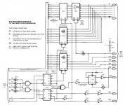
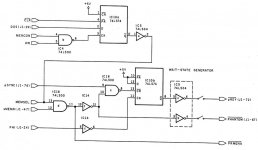
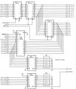
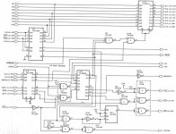
But I'm now half way drawing and I found two little errors in the schematics...
An 7474 was marked ad an 7405, and a 7404 has to be an 7405.
That 7474 was too obvious, but that 7404/5 was a bit nasty... The difference is the open
collector of the 7405. The scans of the color pictures seem to confirm my conclusion.

So I'm a bit worried about other possible errors which I didn't see...

Was there an option to order these PCB's back then? And does anyone know
if there were PCB drawings available?

Regards, Roland
 
If you're just wanting a hard disk interface, John Monahan/s100computers.com has an IDE board for S-100. It uses an Intel 8255 PIA to talk to the IDE device, so there's no issue with 8 vs 16 bit compatibility.

Of course, there's nothing wrong with hacking an old interface onto the S-100 bus, just because you want to :)
 
If you're just wanting a hard disk interface, John Monahan/s100computers.com has an IDE board for S-100. It uses an Intel 8255 PIA to talk to the IDE device, so there's no issue with 8 vs 16 bit compatibility. Of course, there's nothing wrong with hacking an old interface onto the S-100 bus, just because you want to :)

I know :D I've got Johns kicad drawings because the S100 outline is in it. I've never made a PCB using Kicad.
Normally I use Altium. But because kicad is free I can share the drawings with any other hobbyist.
Really, I don't know if anyone likes it or not... But there are a lot SASI-MFM interfaces out there...

So this board gives me the opportunity to use authentic hardware... If it will ever be a success...
You know, time, other projects... But I'm working on it now... Just fun. I guess wire wrapping is just
as much work as drawing the pcb. So why not ;)

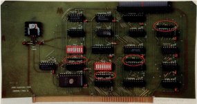
In the meanwhile I see more hardware errors... On the PCB there are four resistor arrays.

resistor arrays.jpg

But not in the schematics...

schema 2.jpg / schema 1.jpg / schema 3.jpg

Yes I can think of where they should be in the schematics. Two of them
will probably be the pull-ups for the address switches..
But there are too many directly visible errors in the document.
So how many invisible errors are there in the document?

I guess I'd better quit this project full of errors... Thanks Byte...

Regards, Roland
 
Last edited:
Hi
The resistor packs are near the components they support. The switches need pull ups so that when they are closed they are low (ground) but when they are open they are high (VCC). Also the pins going to the interface are likely to have pull up resistors. The 74LS38 is open collector so it will likely also have pull up resistors.

Just zoom in on the photo to get clues. Not marking pull up resistors is not really an error and was/is common practice in making schematics. Sometimes they are annotated as asterisks or other symbols or the designer is just expected to know to add them.

Good luck, Andrew Lynch
 
The resistor packs are near the components they support. The switches need pull ups so that when they are closed they are low (ground) but when they are open they are high (VCC). Also the pins going to the interface are likely to have pull up resistors. The 74LS38 is open collector so it will likely also have pull up resistors.

Hi Andrew. Yes, that is the way to check where these pull-ups need to be. No rocket science...

Just zoom in on the photo to get clues.

Yes, that was exactly what I was doing :D Just double checking...

Not marking pull up resistors is not really an error and was/is common practice in making schematics.

Sorry, here I disagree a bit... In my opinion it is really an error because Byte made an article for people to make their own pcb.
A lot of people are not that familiar with designing/building hardware. Besides that, with leaving out those resistors, you are also
leaving out the values of them... Datalines will need a lower Ohmic value then the switches do. But in my opinion you can not
expect from a Byte magazine reader to just know that he should put in pull-ups without even mentioning them in the text.

So by checking the schematics for the pull-ups I found even more errors.
Inputs connected only to inputs (ia0 and ia1), pin numbering errors in components...
Pin labels which can't be found in the other schematics...

I think it is useless to go any further with this project. A waste of time...
It is just very bad documented and there will probably be a lot more errors!

I was wondering if Byte also made correction articles for their projects.


Any other suggestions for a project using old hardware? Or is it better to
just pay $$$ dollar to get a hard disk on a S100 system...?

Regards, Roland
 
Last edited:
I think that Kipp Yeakel ( a member here ) may have experimented with that configuration. Maybe he'll speak up about his experience?

smp

While I do have the drive, controller, and some documents, it is still on the todo list and pretty far down that list as well. Since moving to another state, my electronics shop has not been put back together. Sorry for the lack of help..
Kipp
 
Hi
If there is significant uncertainty about the schematic it might make sense to build a prototype with wire-wrap first to confirm the design. Then once you know it works commit the design to a PCB.
 
Sorry, here I disagree a bit... In my opinion it is really an error because Byte made an article for people to make their own pcb.
A lot of people are not that familiar with designing/building hardware. Besides that, with leaving out those resistors, you are also
leaving out the values of them... Datalines will need a lower Ohmic value then the switches do. But in my opinion you can not
expect from a Byte magazine reader to just know that he should put in pull-ups without even mentioning them in the text.

So by checking the schematics for the pull-ups I found even more errors.
Inputs connected only to inputs (ia0 and ia1), pin numbering errors in components...
Pin labels which can't be found in the other schematics...

I think it is useless to go any further with this project. A waste of time...
It is just very bad documented and there will probably be a lot more errors!

I was wondering if Byte also made correction articles for their projects.


Any other suggestions for a project using old hardware? Or is it better to
just pay $$$ dollar to get a hard disk on a S100 system...?

Regards, Roland

Yes, I agree. That seems unusual for Byte articles to have so many errors. I thought they were better than that. What a shame. I wonder if the project has been taken up elsewhere and updated. Seems like there would be someone at S100computers.com who would be interested in working on a project like that just for the historical purposes.

Good Luck, Andrew Lynch
 
If there is significant uncertainty about the schematic it might make sense to build a prototype with wire-wrap first to confirm the design. Then once you know it works commit the design to a PCB.

Yes, I think that is the best way to go. Somehow I can't get my head off this design.
I've ordered this breakout board http://uxpro.com/shop/index.php?route=product/product&path=65&product_id=72
So I can experiment without using an original S100 experiment board...

I wonder if the project has been taken up elsewhere and updated.

I hope so! If anyone built it please give me an update :D

Seems like there would be someone at S100computers.com who would be interested in working on a project like that just for the historical purposes.Good Luck, Andrew Lynch

Yes, for me it's also the historical part which I like. It is an original design from the end of the S100 time.
I've studied the Xebec S1410 datasheet which gave also some more info. We will see where it ends...

Regards, Roland
 
Back
Top