Eudimorphodon
Veteran Member
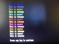
Type in and run the following basic program in BASICA and see what you get:
(20 ends with a semicolon and 30 doesn’t on purpose.)
If the manual is correct the problem will immediately become apparent.
Code:
10 for x=0 to 7
20 color x : print “this is normal “;
30 color x+8 : print “this is intense”
40 next x
(20 ends with a semicolon and 30 doesn’t on purpose.)
If the manual is correct the problem will immediately become apparent.