• Please review our updated Terms and Rules here

SOL-20 0909 PATTERN

All of the 8080 CPU address lines should be operational. However, there is a small part of the cycle where the 8080 manual describes the address bus as "unknown". Now, what the definition of "unknown" actually is...

I would expect to see SOME activity on ALL of the address lines however. The entire address bus should be active for most of the instruction fetch, memory read and write and I/O read and write cycles.

The only thing that would concern me is whether your logic probe would actually sense signals of the frequency that would be present on the address / data bus. I would use a reasonable oscilloscope for this rather than a logic probe to be honest.

I think the logic probe may be telling you lies...

Dave
 
Dave is correct - the address lines should be driven at all times. Are you measuring activity directly on the 8080 CPU IC? If so, it sounds like something is wrong with the 8080 itself.

From what I recall, the address lines are actively driven even during non-bus cycles. This can be seen on a front panel machine like the Altair where you can see the effect of INC and DEC instructions which use the instruction counter incrementer and briefly drive the address bus with the value of the register pair being incremented during instruction execution.

Have you tried a different 8080 chip yet?

Mike
 
Revisiting the address lines on the cpu with the scope, there was indeed square waveform activity on all pins. So, most likely confusion on my part interpreting my newly acquired logic probe.

Still figuring out how to correctly set up my scope for capturing the first four cycles of the phantom signal after reset, but I do know the logic is where it needs to be after reset, as described by the manual.
 
I would now check the other side of the address buffers to make sure these are OK next.

I suspect your logic probe would have difficulty resolving these signals in the first place. I suspect it to be the wrong tool for the job I am afraid.

Dave
 
On your Sol, be sure the Phantom jumper is installed (F-G)

Enable channel 1 and channel 2 on the scope

Set vertical scale for both channels to 2v/div and time scale to 200 or 250ns/div.

With auto trigger selected, position channel 1 near the bottom of the top half of the display and channel 2 near the bottom of the bottom half of the display.

Change to normal trigger, falling edge, at about 2v on channel 2

Connect channel 2 to RESET on U63p9, or the side of R50 connected to this pin.

Connect channel 1 to the positions listed below, one at a time, for each test run. A test run is initiated by activating RESET from the Sol-20 keyboard.

Get screen shots of each of the following test points as RESET is released. You may have to move your horizontal Trigger position towards the left edge of the display.

U24p1
U24p2
U22p3 or p11
U34p11

Mike
 
I would now check the other side of the address buffers to make sure these are OK next.

I suspect your logic probe would have difficulty resolving these signals in the first place. I suspect it to be the wrong tool for the job I am afraid.

Dave
I did this and verified that signals on the cpu address pins are echoed on the outputs of buffers U68,81,67. Everything looks good to be to this point.

Moving over to the Data Input Mux section, U66 was found to be defective according to my IC tester. I triple checked against 3 other good 74LS253's. Looking at the waveforms on this IC, pins 7, 9, and 13 are anomalous to the same pins on U78, 79, and 65. This could point to why the CPU isn't able to fetch an address (?)

Screen Shot 2022-08-29 at 8.34.23 PM.png
 
On your Sol, be sure the Phantom jumper is installed (F-G)

Enable channel 1 and channel 2 on the scope

Set vertical scale for both channels to 2v/div and time scale to 200 or 250ns/div.

With auto trigger selected, position channel 1 near the bottom of the top half of the display and channel 2 near the bottom of the bottom half of the display.

Change to normal trigger, falling edge, at about 2v on channel 2

Connect channel 2 to RESET on U63p9, or the side of R50 connected to this pin.

Connect channel 1 to the positions listed below, one at a time, for each test run. A test run is initiated by activating RESET from the Sol-20 keyboard.

Get screen shots of each of the following test points as RESET is released. You may have to move your horizontal Trigger position towards the left edge of the display.

U24p1
U24p2
U22p3 or p11
U34p11

Mike
Yep, the jumper’s installed.
I lashed up the scope as best as I could to match your directions although putting it in normal trigger mode for some reason makes the traces disappear.

See attached for U24/1,2 so far. Don’t know if this is what you’re looking for.

In both cases, the bottom trace, 1 didn’t show any movement, but in both cases, trace 2 floated up slowly.
46EBAA77-A69D-42DB-BB04-7B29A080A823.jpeg0D882035-D3EA-4588-A8B4-D02DA1E1438B.jpeg
 
For reference, here's what the Sol manual says about Phantom


!POC also resets all stages of D flip-flop U76 (the phantom


start-up circuit) to zero. On initial start-up, the CPU performs


four fetch machine cycles (refer to Intel® 8080 Microcomputer Systems


User's Manual) in accordance with program instructions. For


each fetch, the CPU outputs a DBIN on pin 17. U76, connected as a


four-stage shift register, is clocked by the inverted DBIN signal on


pin 3 of NOR gate U46. Thus, !PHANTOM, on S-100 Bus pin 67, is active


low (assuming the F-to-G jumper is in) for the first four fetches or


machine cycles. After the fourth DBIN, !PHANTOM goes high. !PHANTOM


is used to 1) disable any memory addressed in Page 0 that has Processor


Technology’s exclusive “Phantom Disable” feature and 2) cause the


Sol program memory (ROM), which normally responds to Page C0 (hex) to


respond to Page 00 (hex). The second function is discussed in Paragraph


8.5.2.
 
U66 is responsible for the data input multiplexing (the top 2 data bits) to the CPU. If this is defective (and you say you have checked it on a chip tester) have you replaced it yet?

I assume most (if not all) of your ICs are in sockets?

There can be other reasons for these pins to be anomalous - but if a (working) chip tester says it is duff - then it probably is. However, it could also have died as a result of another fault - although this would be fairly difficult for a piece of TTL logic (unless the pins were connected to a source of volts that were fairly low impedance (or outside of tolerance)).

Dave
Haven’t replaced it yet since I don’t have any spare 74ls253 on hand. Have some on order that should arrive shortly. Btw, any recommendation for a vendor for chips, other than eBay? Mouser doesn’t carry many of the older ic packages, it seems.
 
Mouser will only (generally) stock modern components. Once older stock is gone - it is gone forever...

Unicorn Electronics?

Dave
 
Jon,

The scope traces make no sense versus the setup I defined. Why are there three traces? Are any of the traces voltage measurement cursors? Is the scope set for storage mode? This will not work unless you use normal triggering and the scope is in storage mode. That should capture a single trigger when reset drops and then hold that on the display for us. If it erases with normal trigger, it sound like the trigger settings are wrong. Make sure your are triggering from channel 2 (RESET) and not channel 1. When setting the original vertical position of the two traces, neither probe should be attached to a signal - we essentially want ground to appear near the bottom of each half of the screen for the two signals.

Mike
 
Well, I went to the local electronics store and lo and behold they actually had 74LS253 in stock. Subbed it into U66 and presto, my prompt has returned.

So, the question of how/why it failed is still something to keep an eye on. It may have gotten compromised when I initially removed and cleaned all of the ICs and sockets.

Still would like to figure out how to do the dual trace/trigger/storage on my scope, so I’ll continue to play with that.

Continuing to test function and loading programs for now.
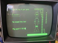
It was probably nothing you did. 74 series TTL can just fail spontaneously, I have had a number do it over the years, typically when I was using the equipment, so they were not really stressed by anything in particular. Something goes awry inside the die with internal corrosion or propagating micro- fractures damaging the circuit. I think Daver-2 does a lot of research on this and even has IC's de-capped to find out "what went wrong".

In most cases the ones that have done this which I have found, have been epoxy cased parts, not ceramic bodied ones. Because of this I have collected a good number of the mil spec 54 series ceramic body TTL's for my stocks and often I use these as replacements for the 74 parts. Having said that I would still rate 74 series & 74LS TTL's as the most reliable and ESD damage resistant IC's in the World.

If you have a look at a PONG board I hand wired back in 2003 (page 96 of the article) I used all ceramic bodied 74xxxJ types or 54 types (all except a few of the total of 66 IC's). So I have always been somewhat enamored & fanatical about the ceramic TTL logic IC's. I have as yet, never found even one defective 54 series TTL. There might be one out there, but they must be pretty rare:

 
Last edited:
>>> presto, my prompt has returned.

Well done...

>>> I think Daver-2 does a lot of research on this and even has IC's de-capped to find out "what went wrong".

We get the odd device de-capped when we start to see the onset of an increasing failure rate.

There are some faults attributable to the IC manufacturing and packaging process going back many years. This is where the JEDEC Organisation and Standards came from (https://www.jedec.org/). Of course, you have to pay for their documents (unless you are a member) or look at the free ones that are floating around the internet. The Standards that have been developed by the JEDEC Committees aim to improve the microelectronics industry. However, some of the older devices can (and do) suffer from some of the failure mechanisms that were identified as problematic in the early years.

One such failure mechanism occurs at the bonding of gold wires to an aluminium pad (just like the internal connecting wires within an IC). This is known as "purple plague" or "purple death". See https://en.wikipedia.org/wiki/Gold–aluminium_intermetallic.

Another problem was the sealing of semiconductor packages from outside contaminants (hermetic sealing). Contaminants would gradually 'leak' into the package and degrade the semiconductor part. This type of failure (and other types of contamination causes) can manifest themselves as initial unreliability as some of the key parameters of the part (e.g. timing) can become degraded over time - before the part fails completely (or badly enough for the circuit to fail - even though the part may actually pass on a 'cheap' chip tester even).

Other causes of internal contamination was the means of bonding the silicon die to the carrier. The bonding agent that was used could leach chemicals that then attacked materials within the silicon die...

Dave
 
On the topic of component ESD resistance, Tek did a great job testing them to find out (see attached). TTL is the clear winner followed by LS TTL.
CMOS,MOS the worst. (as if we didn't know !)
 

Attachments

  • tekj.jpg
    tekj.jpg
    122 KB · Views: 3
So, since getting my SOLOS prompt back, I’ve been able to do the following, with no expansion cards installed:

1. Enter TERM, which as I understand it verifies that the serial port works (?)

2. Memory dump

3. Enter data and read back from memory.

4. Manually entered and ran the small HELLO program.

5. Using Personality module 2708 and adding the 64k Ram card, was able to perform a tape load of a few programs. Realized without the memory card this is not possible even if the program is as small as 300k

Still having issues talking directly to the SOL via my MacBook by serial port. It looks like it could be a pin mismatch, so I’ll need to try a null modem. But so far loading by tape port/wav is working.

Big thanks to deramp and all the wonderful available files!
 

Attachments

  • A1D1154C-2F78-421A-99B5-0478BB629398.jpeg
    A1D1154C-2F78-421A-99B5-0478BB629398.jpeg
    2.9 MB · Views: 8
Back
Top