• Please review our updated Terms and Rules here

Tandy 1000 Keyboard Adapter Reproduction

rkrenicki

Experienced Member
Joined
Jun 21, 2016
Messages
90
I am on a side mission to recreate the Tandy 25-1030 Enhanced Keyboard Adapter for the Tandy 1000/A/HD/SX/TX computers. I borrowed such an adapter, stripped it down, scanned it, and duplicated the layout in Sprint Layout yesterday. I am just putting the final touches on it now, and I will send it off for initial prototype fabrication later today. I also have an image of the ROM which has been written to a new ROM and works perfectly in the original board, so I know it is a good read.

The design is extremely simple, and there is a LOT of wasted space. Once I know for sure that the board does function properly, I will re-do the job in KiCAD with schematics and a new layout. I will make it all open source and post it on my git when I am sure there are no errors.
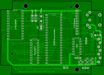
Screen Shot 2020-05-05 at 11.49.31 AM.png
 
I am on a side mission to recreate the Tandy 25-1030 Enhanced Keyboard Adapter for the Tandy 1000/A/HD/SX/TX computers. I borrowed such an adapter, stripped it down, scanned it, and duplicated the layout in Sprint Layout yesterday. I am just putting the final touches on it now, and I will send it off for initial prototype fabrication later today. I also have an image of the ROM which has been written to a new ROM and works perfectly in the original board, so I know it is a good read.

The design is extremely simple, and there is a LOT of wasted space. Once I know for sure that the board does function properly, I will re-do the job in KiCAD with schematics and a new layout. I will make it all open source and post it on my git when I am sure there are no errors.

View attachment 60678

Finally, after all these years...
 
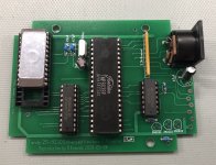
The boards arrived, and I quickly slapped one together (with the sockets that I have.. I ran out of 24 pin wide sockets).. only to find that I never ordered the transistors. I ordered them the other day and they should be here shortly.. but significant progress has been made.

20200512_194422503_iOS.jpg
 
I would be interested in one or two if you're making them available. If not, I can have the boards made.
 
I built a quick and dirty cable today, and my adapter works perfectly on about 1 out of every 3 power-ons. If it comes up and works, it will continue to work until the power is cut to the adapter.

If I manually short pins 5 and 6 on the 74AHCT together a few times, it does seem to kick the latches into working. The original board used a 74ALS373, so I am wondering if the AHCT is just "too fast" for the purpose. I am going to order a couple ALS373s to see if that fixes my problem.

@acadiel I did see that thread, but since it was over a year old I did not want to necrobump it. I know my rom dump is good, I wrote it to a new chip and put that in the original adapter while I still had it to verify correct functions. It does help that I have quite a few NOS 2716 ROM chips kicking around.

I have two board designs, one a direct copy of the original, and one built in KiCAD with a DE9 connector to act as an interface for the Tandy 1000 DIN8 cable. The KiCAD schematic and gerbers are already done since it was such a simple design. Once I am completely satisfied that it works correctly, I will be releasing both designs on git.
 
Looking at the PCB art... are there any bypass caps between VCC and ground for each IC? The "analog" aspects of PCB design are kind of a dark art so far as I'm concerned but recently I was reading an article about why per-chip bypass caps are good practice and maybe it's *possible* you're getting some kind of glitch when that part switches that having it might damp out?

Just for laughs you could try a 10pf cap between pins 10 and 20 on the latch and see if it makes any difference.
 
It does not. It has two ceramic caps for the crystal, and two electrolytics otherwise.
 
I did just throw on a 0.1uF MLCC on the 373, with no change in behavior.

The little trick with shorting pins 5 and 6 together was an accident when I was probing around with my scope and it suddenly started to work when I slipped with the tip of the probe.
 
I can't think of any good reason why shorting those two together should fix anything, given they're outputs to the address lines on the 2716 instead of inputs or control lines to the latch. Maybe the glitch is actually in the EPROM?

A lame idea might be to get a couple nice weak resistors (10k-ish) and try them in both a "pull up" and "pull down" position on those lines, to see if it massages the signal from that latch to something the old EPROM likes better.

(And a bypass on the EPROM might also be worth a shot.)
 
Well, the original design does not have bypasses. This is a 1:1 copy with no modifications whatsoever. The ROM did work perfectly in the original board, so I have a hard time pointing a finger at that. It is exactly the same make and model of ROM chip as well. The traces on the PCB are in largely the same configuration, except I took normal 45 degree turns instead of curved or right angles from the original hand-drawn layout. I cannot imagine that the slight change in trace length is causing a problem here.

The only real place I deviated here is in the family of the 74 series logic. I went with a 74LS05 instead of 7405, and a 74AHCT373 instead of 74ALS373.

So, the AHCT outputs can only sink 8mA when low, and the ALS can sink 24mA. I wonder if my shorting the two pins together momentarily is sinking enough current to get past whatever is keeping it from starting. I am using original Toshiba 8039's from 1984, and 2716 EPROMs of a similar vintage. I could completely see them being too "power hungry" for my low power logic choice.
 
If that is the problem a set of pull-downs might help get you over the hump until your LS chips come in, assuming that is the issue, but maybe it's not worth the bother.

The original board may well have gotten away fine without bypass, but that doesn't mean it's not good practice to include it. Of course I'm sure there's lots of old graybeards listening who'd have a more educated opinion.
 
The original board may well have gotten away fine without bypass, but that doesn't mean it's not good practice to include it.

I do agree with that. My KiCAD version does have them, just because it is old habit. I also included a fuse inline, since we are talking about the keyboard.
 
This is so awesome. I have a 1000SX with no keyboard. :-/ I am unfortunately no help with the stability issues.

Well, once I have the kinks ironed out, I will have to send one your way. Speaking of which, did you see my last email? My email has been acting up and a lot of things have been going to junk mail or not being delivered at all..
 
How long is the reset pulse and how fast does the crystal take off. Some time the crystals can be fussy and like more or less time to come up to full level. The reset pulse has to be long enough to account for this. It doesn't hurt to make the reset longer. You might also try some different amount of capacitor on one side or the other of the crystal.
Dwight
 
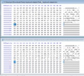
I was able to compare his EPROM dump with mine. His is on the top, and mine is at the bottom.

His @>0000 = 00
Mine @>0000 = 04

His @>0080 = 00
Mine @>0080 = FF

differences_keyboard.png
 
If that is the problem a set of pull-downs might help get you over the hump until your LS chips come in, assuming that is the issue, but maybe it's not worth the bother.

The original board may well have gotten away fine without bypass, but that doesn't mean it's not good practice to include it. Of course I'm sure there's lots of old graybeards listening who'd have a more educated opinion.

Or this was a Tandy Engineering shortcut to save a few cents, and it worked without it, so that's what they went with. Paul T. Schreiber might know who made this converter. I'll point him to this thread.

Edit: Paul states: "The design engineer was Jerry Ballard, who went "off-grid" about 10 years ago. Probably in Idaho."
 
Last edited:
So the ALS chips arrived yesterday, and I am still running into the same issue. I have tried both ROM images (mine, and hexedited a copy to match acadiel's) with the same results on both.

I am starting to suspect either the microcontroller is not working correctly, or perhaps I made an error in the oscillator measurement. These microcontrollers were pulls that I picked up on eBay, so I have no idea what their history is.

I can say with 100% certainty that my ROM image worked on the original board, and I am positive that the schematic PCB is correct. I did add 0.1uF caps to all of the chips, and I also increased the reset cap to 2.2uF to see if that would hold the mcu in reset a little longer... neither of which worked. I also changed the 74LS05 to a 7405 to match the original design, not that I was having issues on the output side.
 
Back
Top