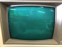
Hello all I'm one of the volunteers over at the Large Scale Systems Museum. We're currently doing some work on a Tektronix 4054 and the problem seems to be the flood gun voltage. The voltage at the test point TP91 starts out within spec but quickly falls to around 55 volts within a few seconds. This circuit is fed from the +290 and +175 rail voltages through a series of transistors. Something is loading down the +175 rail because like the test point voltage it starts out good but quickly falls. I measured the current through the fuse and it went to a few hundred mA before I shut it off. Has anyone encountered a similar problem or perhaps have some insight? Thanks.
Upcoming Events:
- VCF South West - June 14 - 16, Davidson-Gundy Alumni Center at University of Texas at Dallas
- VCF West - Aug 2 - 3, Computer History Museum, Mountain View, CA
- VCF Midwest - Sept 7 - 8 2024, Schaumburg, IL
- VCF SoCal - Mid February 2025, Location TBD, Southern CA
- VCF East - April 2025, Infoage Museum, Wall NJ
-
Please review our updated Terms and Rules here
You are using an out of date browser. It may not display this or other websites correctly.
You should upgrade or use an alternative browser.
You should upgrade or use an alternative browser.
Tektronix 4054 flood gun voltage
- Thread starter epitaxial
- Start date
nikola-wan
Veteran Member
I assume you have the Tektronix 4054 service manuals? The first manual contains the architecture and theory of operation of the various boards.
If you don't - here are links:
I haven't had issues with the high voltages on my 4054.
If you don't - here are links:
I haven't had issues with the high voltages on my 4054.
daver2
10k Member
Hmm...
I can find the +175 VOLTS (UNREG) source and where it goes to on the interconnect board.
According to the schematics for the interconnect board, this supply goes to J130 (deflection amplifier) and J10 (high voltage and Z axis). However, I can't find where these two boards actually use the +175V supply...
Can you point me to the schematic that you are describing - or copy and paste the schematic into your post.
EDIT: Ignore my post - I have just found it...
Dave
daver2
10k Member
Just to confirm - you measured the current flow in fuse F137 as being a few hundred mA? This fuse appears to be rated at 150 mA (0.15A) so that should have blown the fuse (assuming this fault existed prior to you measuring the current flow).
You could see if the problem is isolated to the DOUBLE ERASE STORAGE BOARD by disconnecting resistor R14 (10 Ohms) on the DOUBLE ERASE STORAGE BOARD.
If this fixes the problem with the +175 VOLTS (UNREG) current flow - at least we know the problem is associated with the DOUBLE ERASE STORAGE BOARD.
I would also suggest looking at the state of R14 and the resistors around the flood gun circuitry to start with. Do any look 'fried'?
I can't see any capacitors in there - so that is one issue ruled out.
The only other thing I could think of is something getting too hot. This causes a larger current to flow, which causes the component to heat up further (i.e. a positive coefficient feedback loop).
Let me think on this one...
I am trying to avoid the suggestion that the CRT flood gun anode is shorted to something internally - thus drawing a large current from anode to (say) the cathode (0V)...
Dave
Just to confirm - you measured the current flow in fuse F137 as being a few hundred mA? This fuse appears to be rated at 150 mA (0.15A) so that should have blown the fuse (assuming this fault existed prior to you measuring the current flow).
You could see if the problem is isolated to the DOUBLE ERASE STORAGE BOARD by disconnecting resistor R14 (10 Ohms) on the DOUBLE ERASE STORAGE BOARD.
If this fixes the problem with the +175 VOLTS (UNREG) current flow - at least we know the problem is associated with the DOUBLE ERASE STORAGE BOARD.
I would also suggest looking at the state of R14 and the resistors around the flood gun circuitry to start with. Do any look 'fried'?
I can't see any capacitors in there - so that is one issue ruled out.
The only other thing I could think of is something getting too hot. This causes a larger current to flow, which causes the component to heat up further (i.e. a positive coefficient feedback loop).
Let me think on this one...
I am trying to avoid the suggestion that the CRT flood gun anode is shorted to something internally - thus drawing a large current from anode to (say) the cathode (0V)...
Dave
Hello Dave. Yeah the 150mA fuse didn't blow, but it appeared to be corroded and have a high resistance. When I went to remove it from the clips the metal ends fell right off the glass! The other 150mA fuse also fell apart when it was removed. I measured the current at the fuse holder. Nothing immediately stood out as looking bad on the board but disconnecting that 10 ohm resistor seems like a good starting point. The final transistor driving the flood gun is a TO-220 style so it shouldn't be too difficult to lift the emitter pin and measure the current going to the CRT. Fingers crossed that the CRT doesn't have a problem internally.
daver2
10k Member
Hi,
Yes, I was going to say that the last flood gun transistor driver should have some form of heatsink on it (as this is shown on the schematic) - so it is expected to run warm/hot.
Crossing fingers, toes and anything else...
Dave
Yes, I was going to say that the last flood gun transistor driver should have some form of heatsink on it (as this is shown on the schematic) - so it is expected to run warm/hot.
Crossing fingers, toes and anything else...
Dave
Ok good news to report. My initial current readings were incorrect. After inspecting and re-seating the card and also noticing another loose ribbon cable, things are looking much better. At first it looked like this.
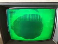
After a few power cycles the display is near perfect, but only every other power up.
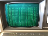
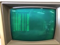
More troubleshooting to be done but fantastic progress given the initial state of this thing. The basic ROM seems to have suffered bit rot and we're working on getting something compatible to replace it.

After a few power cycles the display is near perfect, but only every other power up.


More troubleshooting to be done but fantastic progress given the initial state of this thing. The basic ROM seems to have suffered bit rot and we're working on getting something compatible to replace it.
daver2
10k Member
Moving forwards...
Dave
Dave
stepleton
Veteran Member
I'm faintly interested in this:

That "For" doesn't line up with the others. Alignment is tricky for CRTs but I had a very similar problem:
The culprit turned out to be cracked solder joints on the "Low Voltage Power Supply" board at the base of the case:
PS: That blotchy display doesn't look too abnormal --- does it go away if you clear the screen? (You might not be able to clear the screen while the diagnostics are running, though...)
I'm faintly interested in this:
View attachment 1249106
That "For" doesn't line up with the others. Alignment is tricky for CRTs but I had a very similar problem:
The culprit turned out to be cracked solder joints on the "Low Voltage Power Supply" board at the base of the case:
PS: That blotchy display doesn't look too abnormal --- does it go away if you clear the screen? (You might not be able to clear the screen while the diagnostics are running, though...)
Good catch. It might explain the weird power up behavior. You're right about not being able to clear the screen when the diags are running.
nikola-wan
Veteran Member
Congratulations on your 4054 repair progress!Ok good news to report. My initial current readings were incorrect. After inspecting and re-seating the card and also noticing another loose ribbon cable, things are looking much better. At first it looked like this.
View attachment 1249103
After a few power cycles the display is near perfect, but only every other power up.
View attachment 1249104
View attachment 1249105
More troubleshooting to be done but fantastic progress given the initial state of this thing. The basic ROM seems to have suffered bit rot and we're working on getting something compatible to replace it.
From these ROM Checksums you have the same v5.1 4052/4054 Firmware as my 4052 - which is the latest firmware I have seen reported for the original 4052/4054 hardware.
My 4054A has v1.5 A-Series EPROMs - so all the CRCs are different than my 4052.
Your next step in repair will be the bad DRAM error reported by the Diagnostic ROM. This diagnostic stops at the first error - so after that DRAM is replaced you will need to rerun and see if that fixes your DRAM issue.
Last 4054 I repaired this summer had multiple bad DRAMs in the low memory (which are soldered directly to the main board) and high memory (which are socketed).
I purchased these DRAMs for the 4054 repair - they worked fine! MOSTEK MK4116N-3GP MK4116N-3 4116N MK4116P 16 PIN DIP IC - YOU GET 5 PIECES
Congratulations on your 4054 repair progress!
From these ROM Checksums you have the same v5.1 4052/4054 Firmware as my 4052 - which is the latest firmware I have seen reported for the original 4052/4054 hardware.
My 4054A has v1.5 A-Series EPROMs - so all the CRCs are different than my 4052.
Your next step in repair will be the bad DRAM error reported by the Diagnostic ROM. This diagnostic stops at the first error - so after that DRAM is replaced you will need to rerun and see if that fixes your DRAM issue.
Last 4054 I repaired this summer had multiple bad DRAMs in the low memory (which are soldered directly to the main board) and high memory (which are socketed).
I purchased these DRAMs for the 4054 repair - they worked fine! MOSTEK MK4116N-3GP MK4116N-3 4116N MK4116P 16 PIN DIP IC - YOU GET 5 PIECES
For the soldered chips is there a way to determine which chip it is from the memory address?
nikola-wan
Veteran Member
The Tektronix 4052/4054 Diagnostic ROM Pack manual on Jos' website has the documentation on how to map the memory test error code to a particular DRAM.
stepleton
Veteran Member
Don't forget to run the Option 30 RAM tests when you can --- I know this particular machine to have Option 30 fitted 
nikola-wan
Veteran Member
Wow - a third 4054 with Option 30?
Yes, when I repaired a 4054A with Option 30 in August - both the 4054A and Option 30 had several bad DRAMs, and the Diagnostic ROM pinpointed their locations and we fixed both 4054A and Option 30 with the same 4116 DRAMs.
Yes, when I repaired a 4054A with Option 30 in August - both the 4054A and Option 30 had several bad DRAMs, and the Diagnostic ROM pinpointed their locations and we fixed both 4054A and Option 30 with the same 4116 DRAMs.
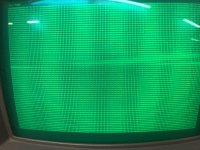
Been a bit slow with the holidays but there has been a significant improvement. The bad ram chip has been replaced and we were able to run some code! The built in rom basic appears to be working fine. This is part of the program specified in the calibration procedure. The banding effect with the sharpness of the characters seems strange but I still need to finish up the work on the power supply. Now this model has graphic option 30. Is option 31 the additional red gun?

stepleton
Veteran Member
That's right re Option 31, although I think the amber colour comes from the make-up of the phosphor (or some other feature of the screen) --- there's no separate gun.
nikola-wan
Veteran Member
Wow - likely just the intensity adjustment might fix the overly bright text! You are almost there!Been a bit slow with the holidays but there has been a significant improvement. The bad ram chip has been replaced and we were able to run some code! The built in rom basic appears to be working fine. This is part of the program specified in the calibration procedure. The banding effect with the sharpness of the characters seems strange but I still need to finish up the work on the power supply. Now this model has graphic option 30. Is option 31 the additional red gun?
View attachment 1251607
nikola-wan
Veteran Member
Your 4054 BASIC ROM CRC's match my 4052 v5.1 ROM CRCs - so the checksum program didn't find any 'bit rot'. V5.1 4052/4054 ROMs are the latest ROMs posted so far. The 4052A/4054A series has different MAS and I/O boards with EPROMs instead of ROMs and Patch ROMs and the only version we have seen is v1.5 on mine and Tom's 4054A.Ok good news to report. My initial current readings were incorrect. After inspecting and re-seating the card and also noticing another loose ribbon cable, things are looking much better. At first it looked like this.
View attachment 1249103
After a few power cycles the display is near perfect, but only every other power up.
View attachment 1249104
View attachment 1249105
More troubleshooting to be done but fantastic progress given the initial state of this thing. The basic ROM seems to have suffered bit rot and we're working on getting something compatible to replace it.

