• Please review our updated Terms and Rules here

Testing a Z80 CPU

Jannie

Experienced Member
Joined
Feb 5, 2017
Messages
273
Location
Cape Town
Recently got a batch of Z80 CPUs and wanted to test them for functionality.

I first used a Z80 NOP Tester to test them all. This basically straps the Data lines to 00h and then monitors the Address lines as the CPU cycle through the full memory map. The clock is only about 10Hz, allowing you to se the Address lines with some LEDs.

All 15 Z80's passed this test with all signals looking normal, at least at first glance with a scope.

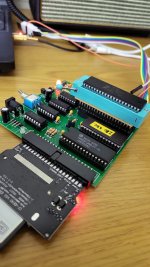
Then I plugged them into a Grant Searle SBC (running around 3.7MHz) and all but 3 booted and ran fine.

The question is thus on the 3 that failed.

Basically; How can one test a Z80 in a test rig type of environment that can give a go/no-go result? The easy answer is to plug it into a computer but that's not the question. I.e. how would you go about testing a Z80 in a structured way?
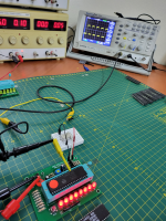

z80-2.png
 
Connect the Z80 up to an EPROM containing a test program.

The EPROM should start at address 0000 and should be activated by the /MREQ and /RD signals going low.

Wire an 8 bit output latch up to 8 LEDs (in series with current limiting resistors). Latch whatever is on the data bus into the latch when /IORQ goes low.

This is only partial decoding, but serves our needs.

Wire up a clock and a reset signal along with a few pull-up resistors on critical control signals.

On a reset all of the LEDs should illuminate.

The test program should start off by writing a code to the LED latch, and continue to write unique codes as the testing proceeds and passes the individual tests.

The test program should halt if it fails. You can illuminate an LED if you wire one up to the /HLT pin of the Z80. The LEDs indicate the last test to pass successfully.

The test program should start off very simple and get more complicated.

You may require some RAM as well as EPROM though.

Perhaps consider an I/O devices containing RAM and I/O?

That is my first suggestion...

Dave
 
As you said, the "easy answer" is to plug it into a computer. However, that is also the best answer and any tester designed to rigourously test a Z80 would run the chip under the same conditions it would be running when in actual use - basically, what Dave suggested above. Just use a simple inexpensive Z80 SBC for this purpose, and outfit it with a ZIF socket if you plan to do this often.
The likely reason your defective Z80s "passed" in the NOP tester is because of the very slow clock rate being tested. Whether the Z80 will run at its maximum rated clock speed is an entirely different matter. Also, while the Z80 may run just fine for a few seconds or minutes, you also want to see whether it can run properly when at its usual operating temperature for a sustained period of time.
 
There is another option...

That is to interface the 5V Z80 address, control and data signals (including the reset and clock) to something like an arduino or Raspberry PI (the 'host') and directly control the Z80 on a cycle by cycle basis from the host processor.

The 'test program' including the virtual ROM, RAM and I/O devices would be emulated within the host.

For example, something like this project: https://www.hackster.io/james-fitzjohn/raspberry-pi-to-z80-interface-0bfbeb.

Notice the use of the Z80 instruction set exerciser. This solution is pretty much what you want, albeit with a cost associated with it for the Pi and I/O.

Of course, this solution can be extended to other CPUs - as long as they are 'static' devices and permit the clock to be stopped. Check the associated CPU data sheet for the minimum clock speed being 0 Hz or DC.

Dave
 
Last edited:
There is another option...

That is to interface the 5V Z80 address, control and data signals (including the reset and clock) to something like an arduino or Raspberry PI (the 'host') and directly control the Z80 on a cycle by cycle basis from the host processor.

The 'test program' including the virtual ROM, RAM and I/O devices would be emulated within the host.

For example, something like this project: https://www.hackster.io/james-fitzjohn/raspberry-pi-to-z80-interface-0bfbeb.

Notice the use of the Z80 instruction set exerciser. This solution is pretty much what you want, albeit with a cost associated with it for the Pi and I/O.

Of course, this solution can be extended to other CPUs - as long as they are 'static' devices and permit the clock to be stopped. Check the associated CPU data sheet for the minimum clock speed being 0 Hz or DC.

Dave
I quite like this. A complete overkill (I've got loads of Z80 systems in my collection for easy testing), but exactly what I'm thinking. :)

In a sense, I love designing and building the test kit even more than fixing the actual target systems. :)
 
After checking the schematic and software there are a few omissions, but these can be added.

For example:

The /INT, /NMI, /WAIT and /BUSRQ pins are pulled up to 5V via a 1k resistor. These pins could be connected to outputs and controlled.

The /HALT, /MREQ, /IORQ, /BUSAK, /M1 and /RFSH pins are not connected to anything. These pins could be connected to inputs and monitored.

Of course, there is no software to drive or monitor these pins, but that could be added...

I was wondering what to do with an old Pi I had...

Dave
 
Of course, you could always use a Z80, EPROM, RAM and a few PIO devices as a host to test the Z80 out 😀!

Dave
 
As you said, the "easy answer" is to plug it into a computer. However, that is also the best answer and any tester designed to rigourously test a Z80 would run the chip under the same conditions it would be running when in actual use - basically, what Dave suggested above. Just use a simple inexpensive Z80 SBC for this purpose, and outfit it with a ZIF socket if you plan to do this often.
The likely reason your defective Z80s "passed" in the NOP tester is because of the very slow clock rate being tested. Whether the Z80 will run at its maximum rated clock speed is an entirely different matter. Also, while the Z80 may run just fine for a few seconds or minutes, you also want to see whether it can run properly when at its usual operating temperature for a sustained period of time.
Indeed. Done this already with a Grant Searle Z80 SBC. The test in this case is to boot the SBC, load CP/M, load BASIC, then load and run a Mandelbrot program. That's how I found the 3 faulty Z80s. But it's not quite the right answer. For example, no testing of IO or memory refresh. :)


Z80-zif.jpg

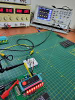
Agree, the clock frequency is a key element. What I've done was to remove the 10KHz 555 and substitute a 1MHz Xtal oscillator.

z80-2.png
From watching the various clock signals, while still executing the NOPs, the CPU seems to be running OK at 1MHz. But that is from my limited understanding of what should be happening.

The issue might well be on something outside the setup with a hard-wired data bus. Writing for example.
 
I think you've approached it just right. Start off with NOP test that won'd hurt the tester if the device is a total dud. If it passed the NOP test, then test it in a barebone computer at 1/2/4MHz for NMOS and 24MHz for CMOS, and then test in a regular computer.

This is a topic (Salvage computing) I'm interested in; with recycled parts so cheap from China but frequently mislabelled, how to build a full computer from these salvaged parts? The popular TL866II can program/test EPROM/EEPROM and has tester functions for TTL logic and RAM. It is desirable to have a barebone computer to check out the CPU and I/O functions.
Bill
 
Indeed. Done this already with a Grant Searle Z80 SBC. The test in this case is to boot the SBC, load CP/M, load BASIC, then load and run a Mandelbrot program. That's how I found the 3 faulty Z80s. But it's not quite the right answer. For example, no testing of IO or memory refresh.
Much depends on how exhaustive a test of the Z80 you think is sufficient.
If the Z80 "passed" when used on a SBC you can be assured that almost all of the Z80 has been tested with the exception of a half dozen pins not typical used on an SBC. The I/O control lines would be tested if the SBC also performs I/O to an attached terminal but those related to use of interrupts, DMA, and memory refresh would not. I suspect there would be very few Z80 chips that test as fully functional with the exception of those few pins.
 
I was thinking maybe the 3 that failed are rated for a slower clock than what was used.
 
Much depends on how exhaustive a test of the Z80 you think is sufficient.
If the Z80 "passed" when used on a SBC you can be assured that almost all of the Z80 has been tested with the exception of a half dozen pins not typical used on an SBC. The I/O control lines would be tested if the SBC also performs I/O to an attached terminal but those related to use of interrupts, DMA, and memory refresh would not. I suspect there would be very few Z80 chips that test as fully functional with the exception of those few pins.
Yup, agree.
 
BTW, did the same with a bunch of 6502 CPUs. First tested them in the NOP generator (clearly a 6502 NOP generator) and then in a VIC-20.
Interestingly, one 6502 that would work in the NOP generator had a very flaky Sync output (pin-7). With the CPU cycling through the addr lines, Sync would stay high and sometimes, randomly start generating a signal. Clearly it did not work in the VIC-20. But I was surprised it seems to be fetvhing opcodes but with no Sync signal being generated.
 
Back
Top