• Please review our updated Terms and Rules here

Using PDPGUI to run BASIC

OK. I have been reading the M9312 manual. It could be that I have a conflict somewhere. There are two kinds of diagnostic ROM, and switch settings that I need to verify. I thought I had it right but I am rechecking everything on this card to be sure. Maybe I can run a diagnostic there that will discover an issue.

I can return to that. For now I will run the tests with the HALT instructions as you've described. Stand by.
 
I started with 2652, changed = 0. Ran from 204. No change.

repated from 2644 - no change
repeated from 2622 - no change

I am not sure why the program would go to this area in the first place, it seems to jump from 204 directly to "the loop"
 
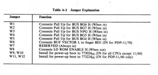
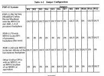
I might have found something...checking the jumpers for my M9312, it appears this was jumpered for an 11/70, with W6 in and W8 out, I never noticed this, I am not sure if this effects the 11/40 or the diagnostics. I am looking at page A-2 of the M9312 Bootstrap/Terminator Technical Manual. According to the manual I need to set jumpers as follows:

"Other Unibus CPUs with an M9312 in place of M9301 or equiv.
W1-W5 in
W6 out
W7 - W10 in
W11 - W12 out.

W6 Connects BUF Vector L to finger BD1 (IN for PDP 11/70), W8 Connects LO ROM ENABLE H (When out). I am going to update the M9312 and try this all again.

I also changed the switches for the ascii console and diagnostic rom to 1 and 7 up, everything else down. I will have to access program manually from 165020. I believe if I put other S1's switches up I'd be calling specific diagnostic routines, but I don't believe I want that.
 
So it HALTS when you put a HALT instruction at 5636 but not when you put one at 2622. Is that correct?

If so, possibly something is going wrong with the IOT instruction.

Can you just double-check what value is stored in memory locations 20 and 22 just after you have loaded a tape and then after it has gone into 'loopy mode' and you have halted it from the front panel please. If memory location 20 or 22 gets corrupted - then the IOT instruction won't work.

Dave
 
I know it's late for you. I will re-load, but right now I am updating the jumpers with my soldering iron, it will be a few hours before I can test. Should have done by your AM.

UPDATE: Started with 6 out and put 8 in. Soon after I took W8 out, it was inhibiting the CONSOLE ROM from running, at least I could not get a prompt unless I removed it. I then re-installed the tape we've been working on and try DaveR's suggestions. (See page 6-1 of M9312, explains why W8 must be out)

values in before
20 / 2622
22 / 0200

loaded 204 into program counter
put 15 up
halts at 20 with data value 201

values after
20 / 2622
22 / 0200

for the fun of it I tried running the program from 200
result - goes into "the loop"

checked values
20 / 2622
22 / 0200

b
b
 
Last edited:
Hi All;

Bill, I'm hoping to get to the point where I am Loading what You are Loading, and see If I get the same thing or different thing than You do, when I try and Run the various programs..
What are You running and where do I get it in Loadable form..

THANK YOU Marty
 
Can you summarize the following

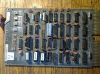
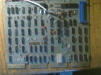
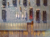
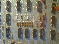
1) are you using a M9312 or M9301? If so, what are the jumpers (or show a good pic)
2) what serial card/settings/jumpers?
3) version PDPGUI
4) what program file are you running, file/module name
5) steps taken to load and run.

In addition to my efforts attempting to load the diagnostic CQKC, today also I double checked the NPG of my entire system and I found that one of the slots I thought was NPG was not, in my DD11C backplane. I removed the NPG / Grant card and replaced with a regular grant card, for this slot.

I updated the jumpers in my M9312 to match the manual, but the system would not allow me to run the console with W8 closed, so I removed it. Not sure what that's all about. There was no difference in the running of the diagnostic after making these changes same issues as before.

I did notice today that now my RT11 controller (m7862) and RL02 drive interact differently. Before the hardware changes just completed I was getting a weird loop on the front panel when I tried to bootstrap the drive to boot. Now, the program runs "something else tbd" and the drive ignores the computer altogether or is not actually being queried, don't know yet. I have thee controllers, all the same response. The system is clearly running when I evoke the bootstrap, just no drive response. I am still focused on the diagnostic, but I was trying other things too.
 
Per the M9312 Technical Manual:

Capture2.JPG

Capture.JPG

For the 11/40, 11/45, etc the last configuration listed should be used to set all the M9312 terminations correctly for that backplane.
The caveat to the last configuration above (W8 IN) is that this will DISABLE detection of the M9312 console emulator PROM.
So in reality to have the M9312 console emulator present and functional (even with the full lights and switches console) the W8 jumper should be OUT.

I will also add that the DIP switch packs as used on the M9312 can deteriorate over time, and even tho the clicker may be moved to one position or another, the switch electrically will be stuck either open or shorted. An ohmmeter check of open/shorted switches is good practice after changing the switch config. Sometimes it takes multiple open/close cycles to fix the connection, or in worst case replacement of the switch pack (or remove/replace with wire jumpers).

I have an 11/34, so I use the configuration on the first line, with the M9312 in A/B of slot 3 of my DD11-PK backplane.
 
Last edited:
Hi All;

Bill, glad Your still hanging in there..

1) are you using a M9312 or M9301? If so, what are the jumpers (or show a good pic)
I am using the M9312,
2) what serial card/settings/jumpers?
M7800,
3) version PDPGUI
None, TeraTerm..
4) what program file are you running, file/module name
ZZ
5) steps taken to load and run.
Put 165020 into the Switch Register, Press Load Address, Press Start..
After I get console Mode Prompt, I type In ZZ and a (CR), and let it rip..

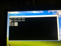
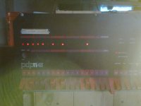
006.jpg 007.jpg


On the M9312, I have the following Jumpers,
W1-W5 IN,
W6 Out,
W7 In,
W8 Out,
W9-10 In,
W11-12 Out..
Switches 1 and 7 up (On)
I can't read for sure but the Console Prom I think is A8..

001.jpg

I also have an M7800 Serial Card, set up as Normal (I think)..

002.jpg


005.jpg 004.jpg

THANK YOU Marty
 
Last edited:
Ok. We are all working from the same playbook with our respective machinery.

It became obvious that I should remove W8 despite the chart and my m9312 presently marches Marty's bit I hAve the rl02 ROM (DL) in the first ROM slot.

I will double check the .rocker switches of S1, anyone in the vintage computing biz for this long knows by now to verify switches, I have replaced my share in the past.
 
Bill,

I think it is your IOT instruction that is going wrong. Can I suggest that you try the following program (this will take the diagnostic program itself out of the equation):

Memory location - Value

40 - 220 ; IOT trap vector
42 - 200 ; IOT trap vector

200 - 012706 ; MOV #600,SP
202 - 600
204 - 240 ; NOP
206 - 240 ; NOP
210 - 4 ; IOT
212 - 240 ; NOP
214 - 0 ; HALT
216 - 0 ; HALT
220 - 0 ; HALT
222 - 0 ; HALT

START the program from address 200.

The program should HALT at 220.

Replace address 220 from 0 (HALT) with 2 (RTI).

Restart from 200.

The program should HALT at 214.

If either of the above doesn't work as expected (i.e. halt at the correct address), try single-stepping the program to see where it goes awry.

The program should load the stack pointer with 600 (instructions at 200 and 202) to point it at a defined piece of memory. Invoke an IOT at address 210. other instructions are either NOPs (240) or HALT (0).

Dave
 
using front panel / HALT CPU

loaded program into RAM from addresses 40 and 200 (did you mean address 40 should have been 240 instead?)

I ran from 200 and it died at address 10, with 200 in data

HALT

load addr 200 then pressed CONT
address lights changed to 204,
CONT
206
CONT
210
CONT
06
CONT
10
CONT
06
CONT
10
etc.

If I change program instruction in 220 from 0 to 2 (010)

I ran from 200 and it died at address 10, with 200 in data

HALT

load addr 200 then pressed CONT
address lights changed to 206
CONT
210
CONT
06
CONT
10
CONT
06
CONT
10
etc.

I am going to try this with 220 in address 240 and 200 in address 242.

UPDATE: No change with 220 in 240 and 200 in 242 (as well as in 40 and 42)
 
Last edited:
Bill,

Your IOT instruction isn't working...

My program (as it stands in post #135) is correct.

Memory address 40 and 42 is the trap vector for the IOT instruction - when the IOT instruction is executed, stuff will be pushed onto the stack and the new Program Counter will be picked up from address 40 (in this case 220) and the program will be continued from this address.

The next question is "why doesn't your IOT instruction work"? This is clearly the reason your diagnostic doesn't work - as it uses the IOT instruction to output messages (which disappears up it's own CPU somewhere).

Dave
 
Just re-reading post #137.

I see you are entering a start address and pressing CONT to run a program. I don't think this works (perhaps other people can chip in here). I think you have to load the start address and press START (not CONT).

Dave
 
Back
Top