• Please review our updated Terms and Rules here

Vectrex blows internal fuse after time

bobmoo79

Member
Joined
Apr 24, 2023
Messages
47
Location
Uk
I bought a Vectrex (3GE version) a while ago and when I received it the unit would power on, and I could hear sound but there was no image. I traced the fault to the power/volume switch. Rather than take the switch apart and clean it I bridged the two terminals on the back so that, when switched, the switch would deliver power to both the logic and monitor circuits. I've since read this is a common problem with the switch and while it's probably better to clean it, this method seems to work fine.

Having done that I decided to recap the machine. bought the caps, carefully replaced one at a time, as I have done on many systems over the years, but now whenever I turn the machine on it runs fine for a short time BUT then blows the internal fuse (250mA T). Generally this is after a minute or so or though I haven't timed exactly. If I replace the fuse, it all works fine again for another minute or so. I've gone through about 10 fuses in the last week but still haven't found the problem. As I didn't spend much time on the system before the recap I actually don't know if this existed before the recap or not. Yes, learning has taken place - properly test the system before tinkering with it too much!

Checks so far:
  • As this seems to be time related I had suspected an issue with the capacitors so I have checked the values and orientation of all capacitors on the logic and power boards and it all looks good to me, aligned to the info on the Console 5 website. Initially I had fitted a standard cap instead of a non-polarised version to C409, but I have corrected that now and the fault persists).
  • For the period the unit is running the voltages on J204 are fine (-5, GND, +5, -13)
  • I have unplugged the logic board and speaker and the problem is still there so I'm confident the issue is somewhere on the power board.
Next steps:
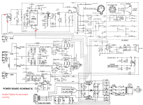
My plan for next steps is to try isolating parts of the power board to see if I can identify which part of the board is an issue. Does this sound reasonable? I've attached an image showing where I plan to tackle this issue (not by making physical cuts to the traces but by removing components).


If anybody has any advice/guidance or a fault-finding workflow for this I'd really appreciate it as I've not worked on a Vectrex before so am not familiar with it.
 

Attachments

  • Vectrex---Power-Board-Schematic Isolate Flyback.png
    Vectrex---Power-Board-Schematic Isolate Flyback.png
    327.6 KB · Views: 14
Could it have something to do with the type of caps used to replace the original? Over in the vintage mac community I've seen people have troubles with certain PSUs when special high frequency or low ESR caps are replaced with the incorrect type.
 
What is the current draw across the fuse? Does it slowly rise as things warm up or does it spike and then pop?

My assumption is it slowly rises until it pops but because I haven't proven it I will do measure it later and report back, though I only have a DVM to do this with. I don't have a current probe for my scope, and I don't think I have a suitable resistor handy to act as a shunt for measuring with my voltage probes (though I will check).

Could it have something to do with the type of caps used to replace the original? Over in the vintage mac community I've seen people have troubles with certain PSUs when special high frequency or low ESR caps are replaced with the incorrect type.

Sorry, I have no idea about this one. I just ordered the correct value electrolytic caps from my local supplier and installed them.
 
To be honest I don't completely understand the specifics behind ESR or high frequency myself, but I do know that PSUs can be picky about stuff like that. Best practice I've heard is to check the series of the original caps and try to replace with the closest available replacements from the same or successor series by the same manufacturer.
 
The problem with disconnecting parts of the internal circuit is that the overall current drawn will be reduced. So all you may have done is to isolate a working piece of circuitry, but the current draw (with the remaining - and potentially faulty - circuitry) is not enough to blow the fuse.

The best thing is to remove the fuse and quickly measure what the current flow is in the fuse with your multimeter. Don't forget, you are playing with the mains voltage side of the transformer here! Again, do this QUICKLY.

The other thing to check is what the value of the internal fuse should be for a UK Vectrex.

Question: Do you have access to a Variac?

Dave
 
Hi Dave, Yes I can see there might be an issue with that. My guess was that a short is being caused and so I hoped that by removing a part of the circuit, if a short occurs on the remaining part that the short would still blow the fuse, even if the current draw is less overall (until the short). Am I wrong?

I definitely have the right fuse according to the sticker on the fuse cover, 250mA (T).

Unfortunately I don't have variac.
 
The best thing is to remove the fuse and quickly measure what the current flow is in the fuse with your multimeter. Don't forget, you are playing with the mains voltage side of the transformer here! Again, do this QUICKLY.

I couldn't quite fathom what you meant here. Did you mean literally remove it from the fuse holder?

In the end i lifted one end of the fuse (leaving the other end in the holder), plugged the vectrex in and put my dvm from the raised end to the empty fuse holder clip, effectively putting my dvm in the circuit. But every time I joined the circuit the fuse blew instantly, so couldn't get a current reading. Is there a better way?
 
There should be two wires connected to the fuse holder. Remove the fuse and see if you can put your meter in series between some convenient point on each of the two wires.

However, I am a little concerned that the fuse keeps blowing with what you are doing...

Perhaps we should rethink this...

Dave
 
I found a more stable way to hook the multimeter up in line with the fuse and was able to repeat the test multiple times. The current draw hovers around 140mA to 160mA when the vectrex is working correctly but eventually the fuse blows as expected. On a couple of occasions the dvm briefly showed a spike of 400+mA as the fuse blew. I have no way of measuring the spike more accurately but I did hook the vectrex up with a 500mA internal fuse once and the result was that it blew, as did the 600mA fuse inside my multimeter, so we can be reasonably certain the current exceeds this amount. 🤣
 
Last edited:
It might be worth trying to isolate the + and - 9V from the high voltage part of the circuit if you can (feeding T503).

You could then see what the static current is when you turn it on, and whether the current increases with time.

If this didn't occur, the problem is in the high voltage circuit. If this does occur, the problem is not in the high voltage circuit.

Dave
 
Successfully removed the -9v and +9v from T503 (by lifting the input legs of T503) but the fuse still blows after about a minute of operation. I'll call that a success (I'll take every win where I can)

So that narrows the search a little bit, eh?
 
One thing I've noticed is that when the system is first powered on in any given day, it will last 2 to 3 (even a bit more sometimes) minutes before blowing the fuse. During my troubleshooting, after this first attempt it usually lasts about a minute.

Might not be significant but it's interesting to note (to me at least)
 
Oh and I found this on the floor this morning. It's an insulating sleeve that should be on one of the legs of one of these caps, but I'm not sure which one. It must have fallen off while I was recapping the board. Again, may not be significant but it sure would be good to be able to put that where it belongs.
 

Attachments

  • 16833161101092675659766044863678.jpg
    16833161101092675659766044863678.jpg
    1.4 MB · Views: 3
There were only 2 caps I remember seeing with a sleeve on. I've found this one (c508) but I can't see the other. I think it should be one of the two caps above it but I might be wrong. C507 and c516. Do you happen to know?
 

Attachments

  • 16833162820626217539097198389684.jpg
    16833162820626217539097198389684.jpg
    1.3 MB · Views: 8
Just before I gave up for the night I revealed IC401 by removing the giant heatsink. Its not obvious to me which pins are +9 and -9v though. I could buzz it out with my DVM to figure it out tomorrow I guess, but do you know?
 
Back
Top