miata
Experienced Member
Hi,
I hope one of the Vectrex experts here can help me with my odd Vectrex issue. I am Denis from Germany and maybe some of you remember me regarding my Commodore PET restauration 3 years ago. I remember very well the help I got from Dwight, the 2 Dave´s (daver_m & daver2) and others from this nice VCFED Forum and I can tell today my Pet is still working fine.") Over time I have learned a lot in electronics and bought also some helpful equipment (logic probe, DVMM, scope, de- soldering iron, etc..) which allowed me to fix also some other nice retro computers so far. A few months ago I found my Vectrex and got the "Vec Fever".
Over time I have learned a lot in electronics and bought also some helpful equipment (logic probe, DVMM, scope, de- soldering iron, etc..) which allowed me to fix also some other nice retro computers so far. A few months ago I found my Vectrex and got the "Vec Fever".
It was running fine until I decided to change out all electrolytic and polystyrene caps. The reason for this - I was not quite happy with the geometriy of the vectors. Since then I am in trouble with my Vetrex. Something went wrong. I overseen that during the recap I bended C324 in such way that it got contact with the 5 VDC leg on the J204 connector when I put the plug on. I stupidly overseen it. So there was a short between +5VDC at the connector and the GND side of the capacitor. When I tried to start up the vectrex the first time after the recap it did not start at all. Then I found that shortcut at J204 and fixed that. Maybe that caused my issue - I dont really know. But maybe not. Because since then the Unit always starts up and I can hear the sound from Mine Storm. But I did not always get a picture. I figured that the -13 VDC was missing when there was no picture. Changed out C12, C121, C122 without any improvement. Something prevented to establish the -13VDC. What helped me in the recent weeks was to start the unit while having the J204 disconnected - power down and re- connect J204. Then the Vectrex was always good to go for 1-2 days or so. Then after that time the screen failed again so I repeated that workaround which used to help for weeks. In the meantime I was trying to understand what can cause that problem and finally I replaced all diodes in the -13VDC circuit (D106, D107, DZ102). It did not help to start the screen in the first place so I needed to repeat my work around. You can imagine that I am getting crazy overtime. But I dont give up yet.
Unfortunately it now became worse. Since saturday the vectors are completely faulty. The game is playing fine though. I can hear the sound and control the game but the vectors are far off. Today I realized a strange thing. When pushing the joystick all the way left and to the bottom the screen looks almost ok. Not really ok but I can read the text and the geometry of the vectors are improving.
Does anybody know what could be broken on my Vectrex? I have attached some photos:
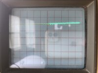
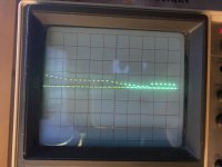
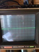
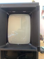
1.) Minestorm without pushing the joystick
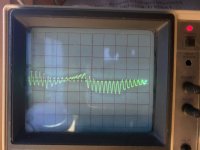
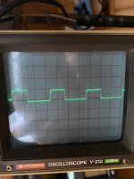
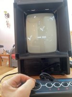
2.) Minestorm with Joystick left/down
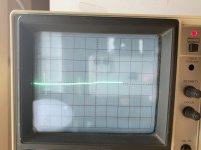
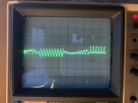
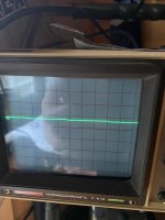
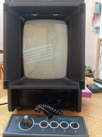
3.) Test Cart V4, first screen without pushing the joystick
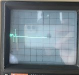
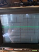
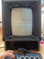
4.) Test Cart V4, first screen with Joystick left/down
This is what I also already did and checked:
- I cleaned the switch (perfect continuity between the poles) and there is ca. 10VAC at EP104 and EP106
- I measured the -9V and +9V at T401
- I can measure -4,98VDC, +4,92VDC and -13,65VDC
- I changed the VIA 6522 and tried 3 different chips - there is no change on the symptoms
- I checked with my logic probe the digital inputs at the DAC chip IC301 - pulses on all pins
- I changed out IC301 - no change
- I have checked continuity of the X,Y,Z Axis signals between the digital and analog board
- I measured VDC for the X,Y, Z Axis at the analog board and get between some mV and 1,x VDC which is changing when I move the joystick. Not sure whether thats normal?
One more thing. I was on a business trip since monday and when I turned on the vectrex today the screen went immediately on. So this is already an little improvement...
best regards
Denis
I hope one of the Vectrex experts here can help me with my odd Vectrex issue. I am Denis from Germany and maybe some of you remember me regarding my Commodore PET restauration 3 years ago. I remember very well the help I got from Dwight, the 2 Dave´s (daver_m & daver2) and others from this nice VCFED Forum and I can tell today my Pet is still working fine.
Over time I have learned a lot in electronics and bought also some helpful equipment (logic probe, DVMM, scope, de- soldering iron, etc..) which allowed me to fix also some other nice retro computers so far. A few months ago I found my Vectrex and got the "Vec Fever".It was running fine until I decided to change out all electrolytic and polystyrene caps. The reason for this - I was not quite happy with the geometriy of the vectors. Since then I am in trouble with my Vetrex. Something went wrong. I overseen that during the recap I bended C324 in such way that it got contact with the 5 VDC leg on the J204 connector when I put the plug on. I stupidly overseen it. So there was a short between +5VDC at the connector and the GND side of the capacitor. When I tried to start up the vectrex the first time after the recap it did not start at all. Then I found that shortcut at J204 and fixed that. Maybe that caused my issue - I dont really know. But maybe not. Because since then the Unit always starts up and I can hear the sound from Mine Storm. But I did not always get a picture. I figured that the -13 VDC was missing when there was no picture. Changed out C12, C121, C122 without any improvement. Something prevented to establish the -13VDC. What helped me in the recent weeks was to start the unit while having the J204 disconnected - power down and re- connect J204. Then the Vectrex was always good to go for 1-2 days or so. Then after that time the screen failed again so I repeated that workaround which used to help for weeks. In the meantime I was trying to understand what can cause that problem and finally I replaced all diodes in the -13VDC circuit (D106, D107, DZ102). It did not help to start the screen in the first place so I needed to repeat my work around. You can imagine that I am getting crazy overtime. But I dont give up yet.
Unfortunately it now became worse. Since saturday the vectors are completely faulty. The game is playing fine though. I can hear the sound and control the game but the vectors are far off. Today I realized a strange thing. When pushing the joystick all the way left and to the bottom the screen looks almost ok. Not really ok but I can read the text and the geometry of the vectors are improving.
Does anybody know what could be broken on my Vectrex? I have attached some photos:
1.) Minestorm without pushing the joystick
2.) Minestorm with Joystick left/down
3.) Test Cart V4, first screen without pushing the joystick
4.) Test Cart V4, first screen with Joystick left/down
This is what I also already did and checked:
- I cleaned the switch (perfect continuity between the poles) and there is ca. 10VAC at EP104 and EP106
- I measured the -9V and +9V at T401
- I can measure -4,98VDC, +4,92VDC and -13,65VDC
- I changed the VIA 6522 and tried 3 different chips - there is no change on the symptoms
- I checked with my logic probe the digital inputs at the DAC chip IC301 - pulses on all pins
- I changed out IC301 - no change
- I have checked continuity of the X,Y,Z Axis signals between the digital and analog board
- I measured VDC for the X,Y, Z Axis at the analog board and get between some mV and 1,x VDC which is changing when I move the joystick. Not sure whether thats normal?
One more thing. I was on a business trip since monday and when I turned on the vectrex today the screen went immediately on. So this is already an little improvement...
best regards
Denis


")