• Please review our updated Terms and Rules here

Vectrex suddenly having faulty vectors

No problem.

It might be worth adding IC303 pin 5 to your oscilloscope list for tomorrow. Let's see what is going into the buffer to only give us a positive Y output on IC303 pin 7.

Let's see what tomorrow brings.

Dave
 
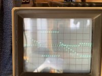
Good morning. Hereby my new scope results.

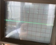
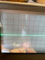
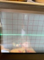
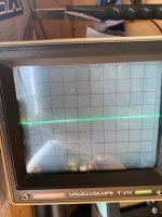
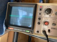
IC207-12 shows a flat line. No wave at all. Tried many settings on my scope. No life here....
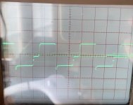
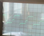
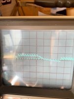
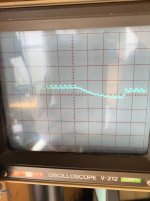
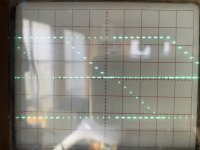
IC207-11 looks similiar as IC302-10 yesterday (scope setting different though: 0,2V/DIV and 50qs/DIV)

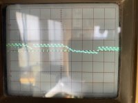
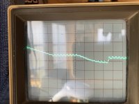
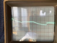
IC305-5 is showing a negative and positive swung therefore I measured IC303-7 again. Similiar picture here! Maybe I did a mistake yesterday?
I used 0,1ms/DIV and 0,2V/DIV for both pins
 

Attachments

  • IC207-11.jpg
    IC207-11.jpg
    972.5 KB · Views: 4
  • IC303-5.jpg
    IC303-5.jpg
    411.6 KB · Views: 4
  • IC303-7 (19.2.).jpg
    IC303-7 (19.2.).jpg
    250.4 KB · Views: 4
It's lunch time again here!

Excellent work though.

I'll get back to you after lunch with more details, but the likely culprit (gut feeling) at the moment is the VIA.

Dave
 
I am definitely erring towards a faulty VIA (IC207).

The only other possibility is something else 'dragging' this line. I would suggest looking at the PCB track from IC207 pin 12 and following it to see if there is an accidental short circuit to something. The other possibility is the IC302 input pin that is shorted out internally.

Are either of these ICs in a socket, or are they not being nice?!

Dave
 
hmm. that´s really strange. I replaced this chip already mutliple times. Luckily it is socketed. Will try again and will look for short at that line now!
 
Ah yes, I see where you have stated that now.

What you can try is to bend pin 12 of IC207 out at 90 degrees to the IC and insert it back into the socket.

See what is on the free pin with the oscilloscope.

If the signal is not there, it either has to be the VIA or further back. If the signal is now there, it has to be the PCB track or IC302.

Dave
 
Just back from testing. Used another 6522 chip - taken from my perfectly working Commodore Pet. I know this one is 100% working. Same story.
I looked for shorts with GND. But between IC207-12 / GND and IC302-9 / GND I measure 1,9 kOhm (powered off) and 0,4 kOhm (powered on).
No short. Would be too easy, right? ;)

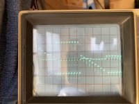
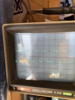
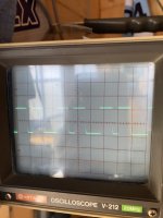
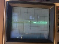
However - I found a signal now at IC302-9. Hardly to see. Just a dot. Took a little video and extracted 2 pictures showing 2 dots. Setting of my scope: 0,5 ms/div and 0,2V/div. This time I connected my external trigger to IC302-10.

Does it make sense what you see?

Having now lunch as well :)
 

Attachments

  • IC302-9a.jpg
    IC302-9a.jpg
    911.6 KB · Views: 5
  • IC302-9b.jpg
    IC302-9b.jpg
    1 MB · Views: 5
At least you can see something now...

The Y scale is confusing me a bit though. These should be TTL signals, so should be switching in the range 0V to at least 4.5V.

At 0.2V per major division, that pulse equates to 0.44V. Have you got a x10 in here somewhere?

Incidentally, the pulses we are probably looking for on the Z output on IC303 pins 10 and 12 might be similar in duration to the pulses you are observing on IC302 pin 9.

You might like to go back and relook at these signals this afternoon with this knowledge in mind.

Dave
 
Dave, you were absolutely right. My probe was set to x10. Oh man I did not recognize that. The switch is very loosen and has been pushed accidently :(
Sorry for that.

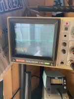
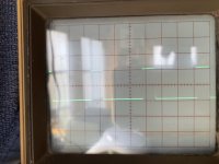
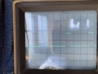
Measured again IC302-9, IC207-11 and IC207-12 (can you see the dot?) with scope setting 0,5ms/div and 2V/div - TTL level now :)
Measured IC303-10 and IC303-12 with scope setting 1ms/div and 1V/div

Sorry for the bad picure quality - today we got a bright day here and my mobile camera cannot do better. Already covered the screen a bit to get better contrast. Need to look for a better solution...
 

Attachments

  • IC303-12.jpg
    IC303-12.jpg
    963 KB · Views: 4
  • IC303-10.jpg
    IC303-10.jpg
    885.9 KB · Views: 4
  • IC302-9.jpg
    IC302-9.jpg
    2.3 MB · Views: 4
  • IC207-12.jpg
    IC207-12.jpg
    2.5 MB · Views: 4
  • IC207-11.jpg
    IC207-11.jpg
    2.4 MB · Views: 4
Looks promising.

Can we now check the following (some are retests) all with the test cartridge cross-hatch screen displayed:

1. IC303 pins 5 and 7 (Y). Check for both positive and negative voltages.

2. IC303 pins 10 and 8 (Z). These are our narrow pulses.

3. IC304 pin 1 (X). Check for both positive and negative voltages.

4. IC303 pins 3 and 12.

5. IC305 pins 12 and 13 (ZERO). Should be +5V and -5V digital signals.

6. IC305 pins 5 and 6 (RAMP). Should be +5V and -5V digital signals.

Dave
 
Last edited:
Hi Dave, this time I can share nice waveforms. They look all good, don´t they?
Scope Settings:
Test 1. - 4. 1ms/div and 1V/div
 

Attachments

  • IC303-3.jpg
    IC303-3.jpg
    876.1 KB · Views: 5
  • IC303-5.jpg
    IC303-5.jpg
    1.2 MB · Views: 5
  • IC303-7.jpg
    IC303-7.jpg
    1 MB · Views: 5
  • IC303-8.jpg
    IC303-8.jpg
    1,015.2 KB · Views: 5
  • IC303-10.jpg
    IC303-10.jpg
    1 MB · Views: 6
  • IC303-12.jpg
    IC303-12.jpg
    784.6 KB · Views: 5
  • IC304-1.jpg
    IC304-1.jpg
    809.7 KB · Views: 6
Last edited:
Test 5. - 6. (IC305) 0,1ms/div and 5V/div
 

Attachments

  • IC305-5.jpg
    IC305-5.jpg
    1,006.8 KB · Views: 3
  • IC305-6.jpg
    IC305-6.jpg
    876.3 KB · Views: 3
  • IC305-12.jpg
    IC305-12.jpg
    874.2 KB · Views: 3
  • IC305-13.jpg
    IC305-13.jpg
    957.9 KB · Views: 3
Last edited:
Dave, Looking to the schematic and following the path you guided me I guess my issue is on the Analog Board? Or do you see something suspicious on the last pictures?

I can follow up the hunt tomorrow afternoon or in the following days but don’t feel pushed please. You will be probably busy during the working days…
I am not in hurry. I recently bought another, working Vectrex which will probably arrive next week. Maybe a possibility to compare things :)
 
Let me have a look at those traces in more detail tomorrow.

We still have the integrators to look at yet... This is where I suspect the trouble to be...

Dave
 
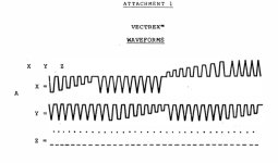
Hi Dave. I am reviewing the waveforms I have taken from J301 for X, Y and Z. X and Y are looking pretty much like in the service manual. But Z looks different. Do you think we should focus more on Z? I have attached the screenshot from Z again.

best regards
Denis

D0CA6DE7-B6E7-4F57-8197-C06AB6A4EC75.jpeg
 

Attachments

  • 5C4CC3C3-A76D-477F-BFAB-7E8128BD44AA.jpeg
    5C4CC3C3-A76D-477F-BFAB-7E8128BD44AA.jpeg
    61 KB · Views: 2
I agree, there is something amiss here somewhere...

Let me describe how I think the Z circuit should work...

That DAC is setup to output a voltage from IC304/1 into the multiplexer IC IC302/13 (IN1). From my understanding, this should be fully positive for 'beam on' and fully negative (?) or 0.0V (?) for 'beam off'.

SEL1 should be set to '1' and SEL0 should be set to '0' with DIS '0' to enable IN1 to OUT1C. In this mode, the input signal from the DAC should be output to the Z channel on IC302 pin 15.

C306 is the sample and hold capacitor. The capacitor is charged up to the analogue voltage that is output on OUT1C.

IC303 (on the Z channel) is a very high input impedance voltage buffer. The output voltage on pin 8 should always be the same as the input voltage on pin 10.

When IC302 pin 6 (DIS) is set HIGH, the output at OUT1C should become open circuit and the voltage that was originally stored on C306 should remain (due to the high input impedance of the following IC303 OPAMP).

Now look at the output of IC303 at pin 8.

If the /BLANK signal goes LOW - this causes the Z signal to go low and blank the beam.

If the /BLANK signal is HIGH - this is the pull-up voltage to turn the beam ON.

However, if the output from IC303 pin 8 goes negative, this drags the Z signal down (via diode D302) and this also blanks the beam.

My expectation is that the Z signal is either ON or OFF (as per the manual) and not as you are observing it.

The question now remains as to why it is like it is. If we can answer this, it may 'open up' the other faults.

Dave
 
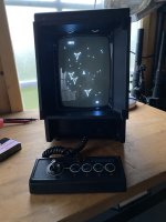
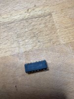
Hi Dave. Thanks for your suggestions. Over the last days I reviewed our troubleshooting and my findings. I wondered why the position of Pot0 and Pot1 influences the vectors and why the Z signal looks weird. I thought maybe IC302 is the culprit. And you know what? It is! I just desoldered the chip and installed a new 4052B with a high quality socket and now my Vectrex is up and running again! Just celebrated with my neighbor with a good bottle of german beer :)

I hope the Vectrex keeps running now. It´s now in an edless Mine Storm Loop for about 1 hour. Fingers crossed...

Thank you very much for your support and help, Dave. You encouraged me not to give up and keep searching:)
 

Attachments

  • B7TKZL9ySXmky4Em3rv6mg.jpg
    B7TKZL9ySXmky4Em3rv6mg.jpg
    1.7 MB · Views: 11
  • +3+mK+EFQCaRcWHs+glMjg.jpg
    +3+mK+EFQCaRcWHs+glMjg.jpg
    2.3 MB · Views: 10
  • Bild 23.02.23 um 18.42.jpg
    Bild 23.02.23 um 18.42.jpg
    113.6 KB · Views: 10
Last edited:
Well done on the repair.

Yes, I remember German Beer :)... However, no repairing computers after a Stein (or more)!

So the fault was as per my hunch back in post #2!

As other people know, I like to be fairly sure before the soldering iron gets warmed up for circuit surgery.

IC302 was certainly not completely defective. That is always annoying and does waste a bit of time. I wonder if a bit of freezer spray or a hair dryer would have exacerbated the fault?

Still - happy minestorming!

Always wise to soak test after a repair as well...

Dave
 
Yes, you put your money on the right horse, Dave. :cool: And I enjoyed the troubleshooting with you. Is the chip one of those which more often fails?
 
Back
Top