• Please review our updated Terms and Rules here

Vectrex with really hair pulling strange -13v problem..

kbjunkie

Member
Joined
Dec 11, 2023
Messages
11
Hi all,

I've been repairing a Vectrex that I bought and I have come across a strange issue.

Background:

When I got it, it had sound but no picture apart from a white dot in the centre of the screen. I thought maybe the main switch had an issue. I tested it and both poles appeared to switch correctly and had continuity, but I took it off the board, took it apart, cleaned the poles and run some deoxit into it and reassembled. The switch works like a charm and both poles read about 1R when the switch is operated.

I put it back in and.. same issue. Sound but no picture.

Checked that the AC inputs to the power board were reaching it when turned on - all good - around 10.8vAC from each red to the white CT wire.

All other voltages at the power plug on the logic board are there - +5,-5 but no -13v. Found that D107 was shorted and the 13v zener was dead too. Replaced those and still no -13v. Checked the other diodes in that circuit and all appear good.

At this point I decided to go mad and replace all electrolytic caps and the integrator caps. So far so good. -13V back and the Vectrex was working.

So, forward in time a few days. Powered the Vectrex back up, no -13v!

Checked around the -13v circuit and nothing. The 7805/7905 regs are working fine and outputting the correct voltages.

This is where it gets weird. I turn the vectrex on, get sound (can hear the built in game sound) but have no picture. I check -13v on the power connector on the logic board and again, all voltages are good except the -13v. I decided to pull the plug off the board (with the vectrex turned on) and measure the -13v at the plug to see if it came back and maybe I had an issue with the DAC chip shorting or something and the -13v was still missing......

I plugged the connector back into the power board - and the -13v came back!!? I switched it on and off a few times and the vectrex starts normally.... WTF!?

I leave it unplugged for an hour or so, and switch it back on. NO -13v!! I unplug the power cable from the logic board again and connect it back whilst the vectrex is switched on, -13V comes back!

I should also say that I made up a new molex connector and replaced the 4 wire cable from the power board and the plug end and replaced the socket on the logic board just in case I had a damaged wire / dirty plug/socket.

Can anyone at all make sense of this?

Thanks in advance!
 
Could it be a bad solder joint? My guess is probably somewhere that you haven't soldered yet since those joints are fresh. Ive never owned a Vectrex tho so idk if this is a common issue or something.
 
Could it be a bad solder joint? My guess is probably somewhere that you haven't soldered yet since those joints are fresh. Ive never owned a Vectrex tho so idk if this is a common issue or something.
I have gone over every joint on both the power and logic boards with a microscope and resoldered any that looked even a little bad. It's not that - thanks for the suggestion though. It's a weird problem that I can't get my head around.

Bad solder joints and bad vias/through hole plating are a problem on the Vectrex PCB's but I've made sure that when I replaced the caps, I soldered both sides of the board (left the caps a little up off the board and got a fine tipped soldering iron underneath them).

It's altogether very frustrating as the machine will work fine as long as I power it up, unplug the power connector between the power and login boards and plug it back in.
 
So you only get -13 if you let the unit warm up? Could it be a thermal failure of the regulator?
Hi NeXT,

No. From cold, the Vectrex when switched on will not deliver the -13 supply - it's just completely missing in action from the power board. -9v regulator is fine though. If I then leave the switch in the ON position and remove J204 (the power connector from the power board to the logic board) and then put it back on again, the -13v supply starts up and the Vectrex is good. If I then switch the Vectrex on and off with the main switch, all remains good. If I then leave the Vectrex for some time (say 30mins to an hour) switched off, the same thing will happen again on switch on - no -13v until I pull and replace J204.

I mean, it sounds like it's cap related - but I've replaced all electrolytic caps including the integrator caps (but not the couple of Tants inside come to think about it), and it doesn't appear to be thermal either. Nothing gets over warm at all. I've also socketed and replaced the DAC chip and the LF347 as the sockets that were in the board were single wipe and quite corroded looking.

I have replaced the Zener with a 500mW 13v Zener - I did wonder if this was somehow the issue. Maybe the old type Zener diode in these Vectrex machines had different characteristics than those today? The schematic in the service manual doesn't give a part number, it just says 13v+/-1V @10mA 400mw Zener. I'm not sure about the 10mA spec - any idea? Is this the current that the Zener 'adds' to the circuit?

Apart from that, the PCB's in the Vectrex are really clean..

NO idea what to do - it's got me a little stumped to be honest.
 
That -13v generation is a simple circuit. If you are unplugging J204 and you are getting no voltage from -13 there's only seven discrete components that make up the entire -13v supply.
D107 and D108 are doing your rectification from AC to DC, albeit half-wave. If one of those go open the circuit opens. The Zener I think is being used to keep the voltage around -13v. If it shorted something spiked and it sacrificed itself, but C120 would prevent a dead short going back to the AC supply and blowing the fuse.
I'd suspect D106 or D107 might be thermally failing after some sort of a previous failure event. R106 could also be intermittent. C122 is to filter out ripple. Replace those two diodes as a pair and see what changes.

vct_PSU.png
 
You might want to go over the traces with a magnifier--a hairline-cracked trace can drive you up the wall.
The 10 ma is the amount of current that the diode is rated to pass. Usually, this means that the diode appears as nothing more than a reference for a regulator circuit. So you have unregulated voltage->resistor->diode->ground typically. If the unregulated voltage is too high, you can exceed the current rating of the diode. Clearly, if it's under the zener voltage, you'll have issues as well. If the resistor is open, you'll also have issues.
 
Last edited:
We did have a thread where we had exactly this behaviour on the -13V rail.

I can't remember exactly how we fixed it, but I think we had a few concurrent problems.

The switch could have gone faulty. It is a dual pole switch.

Yep, bad solder joint or cabke connection - especially around EP106.

C120 could also be faulty.

As you say, it could be any of the components, and you just have to work the problem through.

I would suggest trying to track down our other thread.

Dave
 
Looking at the schematic, the 13V zener appears to be on the output of a regular voltage-doubler circuit. That is C120 is charged through D107 on one half-cycle of the AC input; on the other AC half-cycle, D106 charges C121 with the AC superimposed on the DC level that C120 has been charged to (D107 is not conducting) , providing 2x the input voltage on C120.
 
Hi kbjunkie, David is remembering right, I got this missing -13V issues now in 2x Vectrex and on both it was caused by multiple issues:

1. marginally working or dead diodes in that circuit, I replaced all 3: D106, D107, DZ102
2. Bad contacts in that circuit, like I found between EP106 and C120, visually ok but I found bad contact with multimeter in continuity mode: make sure these components are soldered from both sides. That’s a general issue with the Vectrex caused by poor vias
3. Maybe bad capacitors: I replaced C120, C121 and C122

Good luck!

Denis
 
Hi Denis,

Can you tell me which Zener part number you used to replace your 13v Zener?

Thanks,

KbJ
 
I just ordered some according to the spec in the service manual: 13V with 0,4W. The Service manual gives a (GCE?) part number though: 3M1322
 
I ordered some 13v 0.5w Zeners - replaced all 3 diodes and same issue. I wondered if it was something about the Zener that's causing the issue which is why I wondered which part specifically that you ordered.. I just replaced the other 2 with 1N4148's as in the service manual.

Also bridged out the switch in case that was an issue (although it's reading almost a dead short across the poles when switched on) - no change either. C120 was already replaced and I've checked continuity from EP106 to the relevant part of the circuit and it's all good too.
 
What do you read with a multimeter (bearing in mind that some of the voltages are AC and some are DC) as you move through the voltage doubler circuit (all measurements relative to the 0V/GND rail)?

What is the voltage at the following points (with the negative lead of the multimeter connected to EP105):

C120+ when set to AC.

C120- when set to both AC and then DC.

C121- when set to DC.

C122- when set to DC.

Dave
 
Last edited:
Hi Dave,

Thanks for taking the time :)

  • C120+ when set to AC: 10.17VAC
  • C120- when set to both AC and then DC: 5.47VAC and -4.79VDC
  • C121- when set to DC: -7.54VDC
  • C122- when set to DC - just some mVDC reading - for all intents and purposes, nothing
All of those readings taken whilst there was no -13v working.

Mark.
 
Excellent.

So there are some strange readings here...

This circuit is a standard Greinacher voltage doubler.

You obviously have a good AC voltage at C120+

I am expecting the DC voltage on C121- to be higher than that.

Is it possible that diode D107 and/or D106 are faulty or have been installed the wrong way around?

I would remove R106 (or one end of it) to isolate the zener diode and anything on the Vectrex from the voltage doubler - just in case it is shorting out the -13V rail - and then repeat the DC voltage readings on C121-.

We are now down to four (4) components C120, C121, D106 and D107 that could be faulty - or replaced in the wrong way around.

Dave
 
Hi Dave,

Removing one leg of R106, and measuring C121- is now -25.2VDC.

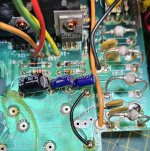
Here's a pic of the area - all diodes look good and in the right way. D107 and DZ102 have already been replaced (D102 was open and I already replaced the Zener with a 0.5w 13v type). I'll away and replace D106 with a 1N4148 same as D107.

Many thanks,

Mark.

EDIT: Just replaced all the diodes - DZ102, D106 and D107. C120/121/122 are new and I've made sure to solder both sides of the board.. still the same issue... :-(
 

Attachments

  • Vectrex.jpg
    Vectrex.jpg
    277.3 KB · Views: 4
Last edited:
I am a little confused now by what you are doing?

If you removed one leg of R106 and you measured in excess of -20V on C121-, then all of the components between the transformer and C121 were fine.

Did I understand you correctly that you then replaced diodes D106 and D107 that were working perfectly OK?

I see you still have les than 10 posts, so are still under moderation.

Can you remove one end of R106 again and check the DC voltage again on C121-.

Report the result but do NOT change any more parts - please...

Is P204 on your machine a real plug and socket?

Dave
 
Last edited:
Hi Dave,

Sorry, my explanation above was bad - I'd previously changed all diodes except D106 (D107/DZ102 were found to be bad), so I replaced that today. I had taken one side of R106 out as you asked and had also unsoldered one side of D106 by mistake. I decided to check that diode since it was out of circuit and instead of reading around 0.6v it was reading 0.34. I thought this seemed a little low and since it was only a 1N4148, I replaced it. That means that I've now replaced all diodes and caps in that circuit (with the exception of R106 which measures 241R - but I thought that was probably okay).

The voltage at C121- is still the same: around -25v - it flicks between -24.2 and -25.2

I'd previously replaced the J204 cables and the plug and socket as the old one was corroded and a couple of the wires had been cut and twisted together with some tape around them by a previous owner (the +5 and -5 cables). I've checked the resistance on each wire from the power board to the bottom of the socket on the logic board and they all measure short.

Many thanks,

Mark.
 
Good morning Mark,

Looks like your Vectrex is really stubborn to get fixed!
You are saying that you checked resistance (continuity?) between the power board and the pins of J204. Did you also check continuity on all connections through the voltage doubler circuit? So, from EP105 and EP106 all the way up to the pins of EP204. Just want to double check that we don’t miss any little detail here….
 
Back
Top