• Please review our updated Terms and Rules here

ZX Spectrum 48K Repair. I could really use some help from the other side of the pond repairing this...

VERAULT

Veteran Member
Joined
Jan 30, 2012
Messages
8,227
Location
Connecticut, USA
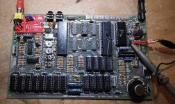
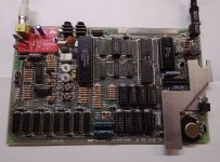
I bought this 48K spectrum at auction a few years ago with the intent of fixing it up for my wife. She grew up with one in Europe so I thought it would be a nice surprise. This is a photo of the board AFTER the modifications I mention below.
IMG_20220120_165323.jpg

ITs an issue 2 board. Using this website as a guide: http://www.breakintoprogram.co.uk/computers/zx-spectrum/hardware I have recapped all the electrolytic caps and replaced all the transistors with the idea that the previous American owner may not have known it was center negative.

I have replaced TR1, TR2,TR3 (which has 4 possible posts on the board although I re-used the same 3), and TR6 which I guess is a ZTX313 and is connected to pins 11 and 30 of IC2 (the Z80) and pin 33 of IC1 (the ULA). I used MPS2369's instead as I read they are compatible for the ZTX313's.

I replaced TR4 which was a ZTX651 with a new ZTX651. I replaced TR5 which was a ZTX213 with a ZTX751 which is supposed to be compatible.

I replaced the 7805 regulator with a new 7805 regulator. Using an ac adapter I modded for center negative the 7805 is getting 10.41V in and 4.98 V out.

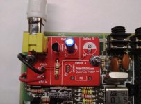
I replaced the RF modulator with the Project Speccy composite mod as seen in this photo.
IMG_20220120_165328.jpg

Other than the power, do I need to do anything additional to get video? Does this thing beep when booting properly? I only get distortion on my screen. I am using the same monochrome green Zenith composite bench monitor I use on everything else. I am getting no life on screen I can see anyway. I could really use some help on this.

Mick
 
No experience whatsoever with speccys, but I'd try bypassing the mod board completely and trying to run the monitor straight from the video line. If that works, I'd probably use the 'option 3' setup on that board. When in doubt, keep it simple.
 
I am starting to wonder if the ROM may be bad. Its a HN613128P. Is this something I can read and verify in my Minipro? If not does someone have the bin file and a method to use an eprom instead?
 
need to check if you have video from the ULA, they fail.

pin 17 is Y (as I recall) with video and H & V sync, this is fed to base of TR1, through TR2 and into the modulator. You should have a video signal on the base of TR2.

This chip should produce a synched screen almost regardless of what else is running.
 
You seem to be concentrating on the +5V supply.

Don't forget that that there are also +12VA, -5V and -12V derived from the +5V supply. Please make sure these are there also.

I can't see from the schematic where the -12V is used.

I see that IC15,... makes reference to +15V on the VDD pin. I don't believe this - I think it should be +5V? I say this because the decoupling capacitors are connected to pin 1 (NC - No Connect) instead of 0V on pin 16 (VSS). I think there are some fairly major errors on the schematic.

In particular, +12VA is used by the video output stage...

After that, I would be checking for a clock on the Z80 pin 6 (this is produced from the ULA itself) and see what signals such as /INT, /IORQ, /MREQ, /RD, /WR, /M1 are doing around the Z80 CPU. They should all be oscillating under normal circumstances.

Dave
 
Oh I know its PAL.
I found that my wifes first generation 4:3 LCD TV accepts a pal signal. I bought one of these video signal generators from Ali express : https://www.aliexpress.com/item/33044563405.html?spm=a2g0o.order_list.0.0.21ef1802ig8WDV so I can test monitors on the road I was interested in purchasing. It creates a PAL signal and this TV I mentioned sees the image.

Sorry for my ignorance. I know very little about the Spectrums and there are very, very few folks here in the US who seem to know them at all. Thank you for the schematic and the service manual.

Let me clear off some bench space and fire up my O-scope. Its been a few years so I need to see if it will even calibrate. IF not all I have at my dispostal is a good meter and logic probe.
 
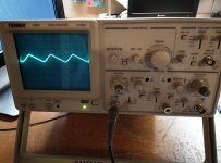
Well I pulled out my Tenma 72-688 O-Scope. Needed a few caps replaced but its working now. Here is a photo I just took of it reading an NTSC signal from the video generator I mentioned in my last post. The waveform looks good enough. I will check the schematics and verify the other voltages and what you both mentioned. Thanks Gary and Dave. Ill post back.
Resized_20220121_185137.jpeg

By the way. What do VR1, VR2, TC1, and TC2 (pots?) do? If they were out of whack would that cause no video out? I was just curious about them.
 
TC1 tweaks the ULA/CPU clock to get the exact frequency as shown on the crystal (or the service manual).

TC2 adjusts the frequency of the chroma oscillator, and may need tweaking if the colour display is intermittent (flips from colour to monochrome).

VR1 and VR2 adjusts the ‘perceived’ colour. VR1 (blue-luminance) and VR2 (red-luminance).

The service manual is pretty descriptive.

Dave
 
Generally, replacing the caps and transistors on a ZX Spectrum isn't necessary and just leads to other potential post-work failures in a Spectrum, except where the regulator transistors are known faulty and there's no -5v and 12v on the 4116 RAM chip bank. TR4 is the usual culprit, and best to try to find a ZTX653 or similar to replace it with IIRC. I've never seen a spectrum in the current era with failed electrolytics. Some that are marginal, sure, but they still work OK.

General steps to getting a spectrum going.

1) Are the address lines oscillating? N = Faulty Z80 or ULA.
2) Is the z80 getting a clock signal? N= faulty ULA.
3) Are you getting video? You should always see a video signal if the ULA is functional, even if the machine is in a bad way.
4) Is there an image? Video ram is the most likely culprit otherwise, and the RAM is the most common failure on the Spectrums I fix. 4116 chips can be sourced cheap from China.
5) Replaced video ram and ULA good but not video ? Check the 74157 MUXs. Rare, but they do break.
6) Download a test ROM, burn to an Eprom, and run some diagnostics. These can sometimes run even if the video ram is shot, and usually try and tell you which chips are not working via bars on the border.

Hope this helps. Schematics for the Issue 2 are easy to google for and find.
David.
 
Ok I did some checks. In regards to IC 15 and Dave you mention of +15V I am in agreement it should be +5V and that is what I am getting.
Using the schematic, I am getting 9.8V from R59, D15, and R62 (so my 12V rail is a problem).
I am getting +10.4V from C46 where the schematic says I should be seeing -12V so I dont know if the schematic is wrong or my board is.
The z80 is getting clock signal.
Reset on the Z80 is stuck high at 4.8V (pin 26)
 
I agree.

It looks like your +12V and (by inference) +12VA - is too low. This could affect the DRAM and the video circuitry.

I still can't see where -12V is used - but I do agree (now I have looked at the schematic again) that the schematic does look a bit suspect.

I would guess that -12V should be at the junction of C46, D11 and R55 instead of where it is shown. Is the -5V rail OK?

Dave
 
"I would guess that -12V should be at the junction of C46, D11 and R55 instead of where it is shown. Is the -5V rail OK?" So yes the 5V rail seems to be the only power voltage that is ok.
I am not getting anything resembling a -5V rail at C46,D11, and R55.

I have removed all the 4116 RAM, verified they are all working (in my Apple II plus) and socketed and put them back in the system.

Any ideas where I should be looking now?
 
What do you see (using an oscilloscope) between TR4 base and emitter (gnd on emitter probe on the base) and TR4 collector and emitter (gnd on emitter and probe on collector)?

TR5 (in conjunction with TR4) is an oscillator - fed from a 5V and 9V supply. If it is not oscillating, you will only get +9V (or so) fed into the subsequent circuitry (which seems to align with your faulty readings).

Dave
 
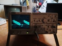
Ok here is the output of the Base and Emitter on TR4:
IMG_20220125_181139.jpg
IMG_20220125_181124.jpg


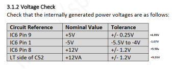
I did the voltage check in the service manual on page 17 and these were my results:
volt check.png

Just thinking here. Some the the transistors I received were not exact matches of the originals. I am wondering if I put a few of them in backwards.
 
Last edited:
Back
Top