- VCF South West - June 14 - 16, Davidson-Gundy Alumni Center at University of Texas at Dallas
- VCF West - Aug 2 - 3, Computer History Museum, Mountain View, CA
- VCF Midwest - Sept 7 - 8 2024, Schaumburg, IL
- VCF SoCal - Mid February 2025, Location TBD, Southern CA
- VCF East - April 2025, Infoage Museum, Wall NJ
-
Please review our updated Terms and Rules here
You are using an out of date browser. It may not display this or other websites correctly.
You should upgrade or use an alternative browser.
You should upgrade or use an alternative browser.
Cannot use EPROM to replace character ROM in 4032.
- Thread starter A4000Bear
- Start date
Nivag Swerdna
Veteran Member
Using my TL866 I could program and verify the devices... but they didn't work in the wild. It was very discombobulating at the time.
Hugo Holden
Veteran Member
Nivag,
Interesting to read about all the trouble, on the eevblog link you posted, people have had programming the 2716. The originals required a 25V Vpp and some programmer units clearly cannot do them reliably if they can barely make it 21V. Then it would not be good to program a lower voltage part with the higher voltage either. Also, there is the speed issue with the smaller sized dies. Probably is a combination of variations in IC and variations in programming protocols & voltages.
The 2716's that have impressed me the most so far, without any problems, programming them in the GQ-4x programmer (which has an external supporting power supply too, not just power derived via the USB link) are the ones made by Fujitsu and the Tesla types. The Tesla Czech mil spec 2716C was made to be compatible with Intel's original part, it is essentially a clone of it. I seem to have a knack for spotting quality IC's, so I bought up a number of them for my stocks, all are perfect and I have not had a single dud. The only issue was that when used as the character ROM in the pet, PIN 21 needs to be tied to V+, not the /INIT line.
Attachments
Nivag Swerdna
Veteran Member
I think the appropriate programmer is the key. AFAIK the GQ-4x does proper 25V programming for 2716s.programming them in the GQ-4x programmer
PS
@Hugo those EPROMS of yours above are very aesthetically pleasing, Nice!
Last edited:
Hugo Holden
Veteran Member
And, the GQ-4x is a cheap and readily available programmer too. I got it initially to program some FM16W08 FRAM's used as substitutes for the DS1225's in my 2465B scopes, but then later it came in very handy for programming a lot of other vintage chips. I also have a BP1400 programmer too, that can do some older chips. As I recall the GX-4x won't do a 2708 but the BP1400 will.I think the appropriate programmer is the key. AFAIK the GQ-4x does proper 25V programming for 2716s.
A lot of programming headaches might vanish if more people got the GQ-4x.
A4000Bear
Experienced Member
I must confess it was so long ago when I last used it, I forgot it supported nothing smaller than a 2764! However I do have a really old home built Electronics Australia programmer, so once I dig out an old DOS PC, I'll give it a try.What a cool piece of Australiana, I have never seen one before. Lucky you !
Guess I should get a CRO and have a look at the Vpp waveform on my TOP3000. It claims to support 25V, but I'm not sure if it really does.
A4000Bear
Experienced Member
My ST 2716s are all the small die variant, though the labelling on them varies slightly. They don't appear to be counterfeits though. My programmer does seem to program and verify them first time, every time, but as discussed in this thread, they seem to have timing issues when used as character ROMs in my 4032. I used one of these for an edit ROM in the same PET, and it worked fine.I'm just visiting this thread for the first time and probably haven't read it completely but...
I would be tempted to bend out pin 21 and add a short jumper wire to pin 24. That way you can be assured that is pulled up hard.
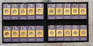
On the subject of some 2nd hand UV EPROMS... I had similar inconsistent behaviour with
View attachment 1250920
my rag tag collection of ST devices I had accumlated from a variety of sources. I was trying to program them with a TL866 and they appeared to work but not reliably... I had assumed that 21V implied they could be programmed with 21V...
Anyway after many days of heartache I did discover they worked reliably if you use an old programmer than honours the 2716 programming spec... I used a Data I/O 29B. Programming in a TL866 just led to disappointment!
More info here... https://www.eevblog.com/forum/proje...fast-uveprom-behaviour/msg3838301/#msg3838301
Look at the dies above.... what a variation!
Your mileage may vary.
A few years ago, before I became aware of the counterfeit problem, I purchased about 24 TMS2532A EPPROMS. I was never able to program them.

A 2009 manufacturing date?....for a 2532?....Yeah, right!
Hugo Holden
Veteran Member
I’ve got some TMS2532A that I think might be faked too. I need to get a microscope or something to see if there is any text on the die that would tell me what they really are, maybe they are still useful for something.
The TMS2532A's are notoriously difficult to program. The arcade game people had a lot of trouble programming them.
It might have been the programming voltages or maybe protocols in the programmers or maybe fake IC's, though it is harder to fake and re-label ceramic bodied IC's and make it look convincing. It is possible to program TMS2532A in the GQ-4x, if they are a genuine part, but it requires that the GQ-4x is set to a 2732A (to get the correct program voltage) and that a socket adapter is made. Because of these issues, I steered well clear of them and only bought TMS2532JL's for my PET and I have had no trouble at all with these and the GQ-4x combination.
Hugo Holden
Veteran Member
Do you know what month & year that one was published ?I do have a really old home built Electronics Australia programmer, so once I dig out an old DOS PC, I'll give it a try.
A4000Bear
Experienced Member
It was late 1993. It was spread over September-October.Do you know what month & year that one was published ?
Last edited:
Hugo Holden
Veteran Member
Thanks,It was late 1993. It was spread over September-October.
EA is online now:

Electronics Australia 1993 : Free Download, Borrow, and Streaming : Internet Archive
Electronics Australia Magazine 1993All issues, scanned at 300 DPI
archive.org
The programmer looks great, it handles the 2716 and it is all programmed in BASIC, with the code provided there, for use with an IBM PC, very good looking project.
A4000Bear
Experienced Member
I bought mine as a kit many years ago, and it came with specially written software, which can be found here: http://alternatezone.com/electronics/eprom.htmThanks,
EA is online now:
Electronics Australia 1993 : Free Download, Borrow, and Streaming : Internet Archive
Electronics Australia Magazine 1993All issues, scanned at 300 DPIarchive.org
The programmer looks great, it handles the 2716 and it is all programmed in BASIC, with the code provided there, for use with an IBM PC, very good looking project.
Radix
Experienced Member
Just to add some info to the thread...
I have been using a stock of these NOS 2716 EPROMS as replacements for the Chr Gen and E000 in recent PET repairs and they seemed to work perfectly OK, but interested to read about problems with 2716s pulling down the /INIT line, so I just did a couple of tests...
When used in the E000 socket, with the 100R pull-up, it drops about 0.5V to 4.5V - but in the Chr Gen with the 1K pull-up on the /INIT line, it pulls down to about 2V! - but the PET visually works fine, although this is clearly NOT fine... so the mod lifting Pin 21 and hardwiring to pin 24 is certainly a good idea...
daver2
10k Member
I have a (small) stock of Intel D2716 devices (25V programming voltage) that I had made back in 2013 or 2016 ish.
They used stocks of Intel 2716 silicon wafers that were sliced, diced and encapsulated in ceramic.
These were for a job at work (so money was no object) but I have a small part of the inventory that I used for qualification testing that can't now be used for the real job.
I also had some Intel 2764 devices made as well for a different card we were manufacturing.
I did this for the reasons already quoted in that you can't 'trust' what is in the 'grey' market. I have a complete paper trail for these devices all the way back to Intel.
If anyone wants one of these devices to test in the character generator socket I can see what I can do to get one shipped to you. I only have a small number of devices though, so I can only spare one or two. I need the rest for my own PET repairs. I may have accidentally booked a few too many out of stores than needed for my own qualification testing purposes. A shame really...
Dave
Hugo Holden
Veteran Member
Dave,I did this for the reasons already quoted in that you can't 'trust' what is in the 'grey' market. I have a complete paper trail for these devices all the way back to Intel.
Dave
This is one reason why I tend to try to find mil-spec parts. They are often more expensive, but they have been subject to more rigorous controls, sometimes in the manufacturing and definitely in the testing and the duds, I think, get weeded out. I often find with vintage mil spec parts (if genuine), it is hard to find dud mixed in with them, that has to be a good sign.
What I really want is to get my hands on is a good assortment of the Space rated mil spec radiation hardened vintage TTL's. Not that they would be getting exposed to radiation around here, but I like the way they went through rigorous examination and qualifications before they let them "escape" from the factory. I think they would be very trustworthy.
Hugo Holden
Veteran Member
Just to add some info to the thread...
I have been using a stock of these NOS 2716 EPROMS as replacements for the Chr Gen and E000 in recent PET repairs and they seemed to work perfectly OK, but interested to read about problems with 2716s pulling down the /INIT line, so I just did a couple of tests...
When used in the E000 socket, with the 100R pull-up, it drops about 0.5V to 4.5V - but in the Chr Gen with the 1K pull-up on the /INIT line, it pulls down to about 2V! - but the PET visually works fine, although this is clearly NOT fine... so the mod lifting Pin 21 and hardwiring to pin 24 is certainly a good idea...
View attachment 1250938
I think I decided, looking at my PET board, if I was going to make this mod, I noticed that the track leading to pin 21, went to an easily accessible plated through hole nearby that was not under an IC. (but I don't know if it is the same track layout in all PETs)
I'm not a fan of cutting pcb tracks, its ugly, but another more elegant way to do it, is to simply run a small drill in the region of 0.8 to 1mm dia through the plated through hole. This effectively disconnects the track leading to pin 21. Then pin 21 can be linked to the +5V with a short length of kynar or teflon coated wire.
Also later, if that modification needs reversing, a link can be placed through the hole to join the pads on either side. So it is a sort of reversible track cutting technique.
Sure pin 21 could be bent out of the IC socket and tied to +5V , that is pretty ugly too and then you cannot pull the IC without un-soldering that pin.
daver2
10k Member
The definition of 'trustworthy' in the industry that I work in is a 'paper trail' back to the Original Component Manufacturer (OCM).
Where this is not possible, you need to have a good justification for use - and some appropriate compensatory measures to 'fill in the blanks' (such as inspection, test and measurement).
It also depends upon where the components are going within the system.
Interestingly, we had a component once (a clock generator) that had no markings at all on the silicon die (when we removed its lid). The silicon die was completely different to the Intel component it was purporting to emulate - so it was clearly a remanufactured or counterfeit part. When tested, it was 100% compatible to the Intel part - so it was clearly a remanufactured part.
A sample batch was tested and was fine.
During manufacture, all of the parts were tested on the Automated Test Equipment (ATE) and all passed. In this case, they all looked to be perfectly suitable, but it was strange that there was no markings on the silicon die (unless the manufacturer didn't want to be identified for fear of being sued by Intel of course).
If these devices fail in use, the failure will be revealed - they are the source of the clock for a CPU.
I haveca friend who used to work in identifying counterfeit parts. He has a 'rogues gallery' of devices in his workshop - ranging from the obvious 'fakes' to the extremely difficult to detect.
One of the interesting parts is a perfectly functional microcontroller that has been remarked as a different variant of the SAME microcontroller. The daft part is that a more costly part (on the open market) has been remarked as a cheaper part. Go figure!
I have also seen colleagues purchase EPROMS from the grey market only to find that they actually fell apart (literally) when they took them out of the delivery package...
Dave
Eudimorphodon
Veteran Member
When used in the E000 socket, with the 100R pull-up, it drops about 0.5V to 4.5V - but in the Chr Gen with the 1K pull-up on the /INIT line, it pulls down to about 2V! - but the PET visually works fine, although this is clearly NOT fine... so the mod lifting Pin 21 and hardwiring to pin 24 is certainly a good idea...
I spent some time looking at the schematics and scratching my head, and... yeah, honestly, after seeing all the things /INIT is connected to it kind of seems like a bad idea to really even claim the 2716 is in fact compatible with the character ROM socket in the PET *without* modifying pin 21. (Either hacking the socket/motherboard, or just soldering a jumper between pin 21 and 24 on the chip after programming and leaving pin 21 out of the socket.) The 2716 is supposed to *always* have 5v on VPP when running under normal conditions. The equivalent pin on the 2316 is a (programmable) CE line that happens to be held to 5v as configured in the PET *through a pull up*. This datasheet says in read mode a 2716 with VCC=VPP can draw up to 5ma, which coincidentally is the most current under ideal conditions that a 5v supply through a 1k pull-up could possibly provide.
There are a number of things in the timing section that are affected by /INIT getting pulled low, including, it looks like, the feed clock to the CRTC. So potentially all kinds of weird stuff could be a knock-on effect if a 2716 in that socket pulled /INIT low enough that its state looked uncertain to other things on that circuit. So... yeah. I'm not at all clear why Commodore felt they needed to connect one of the CE lines of the original ROM to /INIT, I don't really see any reason why that chip *needs* to be tri-stated when all the timing related goo also connected to it is, but it's something I don't think the 2716 can reliably replicate. (IE, going low in VPP is just a "shouldn't happen" condition for that chip, it's not a chip select condition.) I'm really curious now if pulling pin 21 out of the socket and jumpering it to 5v would have fixed the OP's problem. (IE, the only reason it's working now is "sheer luck", IE, some 2716s happen to pull less current on VPP in read mode than others.)
Hugo Holden
Veteran Member
The /INIT pullup line is also a little more tricky than it looks, regardless of the 2716's effect on it. When I first found the problem, naturally the first thing I tried was to pull the /INIT line up with a much lower value pullup resistor to make it go to logic high at least around 3V or more. Interestingly this can cause problems and the computer not boot properly. There is something about the /INIT line, where at power up, if it is pulled up too hard and maybe too fast something goes awry in the timing circuits. I never got to the bottom of it, so I simply decided to "leave it alone" and concluded the better method was disconnect pin 21 of the Char ROM using the drill through via method and link pin 21 of the character ROM socket to V+.I spent some time looking at the schematics and scratching my head, and... yeah, honestly, after seeing all the things /INIT is connected to it kind of seems like a bad idea to really even claim the 2716 is in fact compatible with the character ROM socket in the PET *without* modifying pin 21. (Either hacking the socket/motherboard, or just soldering a jumper between pin 21 and 24 on the chip after programming and leaving pin 21 out of the socket.) The 2716 is supposed to *always* have 5v on VPP when running under normal conditions. The equivalent pin on the 2316 is a (programmable) CE line that happens to be held to 5v as configured in the PET *through a pull up*. This datasheet says in read mode a 2716 with VCC=VPP can draw up to 5ma, which coincidentally is the most current under ideal conditions that a 5v supply through a 1k pull-up could possibly provide.
There are a number of things in the timing section that are affected by /INIT getting pulled low, including, it looks like, the feed clock to the CRTC. So potentially all kinds of weird stuff could be a knock-on effect if a 2716 in that socket pulled /INIT low enough that its state looked uncertain to other things on that circuit. So... yeah. I'm not at all clear why Commodore felt they needed to connect one of the CE lines of the original ROM to /INIT, I don't really see any reason why that chip *needs* to be tri-stated when all the timing related goo also connected to it is, but it's something I don't think the 2716 can reliably replicate. (IE, going low in VPP is just a "shouldn't happen" condition for that chip, it's not a chip select condition.) I'm really curious now if pulling pin 21 out of the socket and jumpering it to 5v would have fixed the OP's problem. (IE, the only reason it's working now is "sheer luck", IE, some 2716s happen to pull less current on VPP in read mode than others.)