• Please review our updated Terms and Rules here

Cromemco dazzler replica project

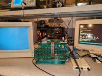
Got my last part! put it all together, fired it up and ran GDEMO.COM and .... nothing!.. tried KSCOPE.COM and .... nothing again. darn.. black screen.

Sanity check: this is meant to plug into a standard composite video monitor right? So an AppleColor Composite or Commodore 1702 should work?

Guess it's time to go back through everything with a fine-tooth comb. The manual gives a test/tuning routine which relies on a front panel which I don't have. Was there any other diagnostics software?
Thanks for volunteering, whatever you find, it will be invaluable. I have also updated your silkscreen findings with the Rev D version.

My problem with the KiCAD files is that it is difficult to check them against the schematics. Most routes consist of multiple segments, which are not easy to check against the schematics when you can't highlight the complete interconnect between pads. Which however normally is the first step, so that you can have your focus on the components rather than on the PCB. But you can of course check the routes relatively easy on the PCB once it has been produced. I guess it is important to make sure all connections are *really* consistant with the schematics before starting to trace the gates.

The components (at least the ICs) in general are old enough that with a certain amount of ICs, always some of them are not fully working. It was interesting that Hugo's board worked from the start. Mostly replicas built with vintage components require some care before they work as expected. This is at least my experience.

I don't know of any diagnostics other than those in the original manual. It is a really great feature to be able to step through the code with a front panel :)
 
What RAM are you using in your machine?

I remember something from the dim and distant past about using static RAM for the memory that the Dazzler uses.

How have you set up the banking?

Just thinking aloud...

Dave
 
I guess it is important to make sure all connections are *really* consistant with the schematics before starting to trace the gates.

It was interesting that Hugo's board worked from the start.:)

I stayed up a lot of late nights verifying the connections with the schematics, despite all that I managed to miss just one pin that should have been tied high (but it assumes a logic high anyway).

One thing that I have learned over many years of fixing faulty equipment is; it can be straightforward, if nobody else has worked on it and a single fault has developed.

If the thing is a new build and never worked in the first place, especially for a complex circuit, then multiple variables could be at play, making it much more difficult. This is why my M/O replicating vintage gear is to try to get it as accurate as possible, to reduce variables that step in to throw the spanner in the works.

Apparently according to a source who worked at Atari, in the 1970's, they found then that 1/100 74 series chips were duds.

Interestingly, this is not my experience of TTL logic chips from that era (memory IC's excluded of course), in that I have built a number of boards like Pong boards with 65 or more nos TTL logic IC's of that vintage and seldom struck a dud, only on very rare occasions. Though I have had a 74 chip in my SOL-20 fail right in front of my eyes and replaced a few 74 series duds here and there in my vintage computers.

I'd guess less than 1/300 myself might be a more realistic "dud rate" for nos vintage 74 series TTL's. Also if the chips are 54 mil spec ceramic versions, nos, never a dud.

It could be as simple as one IC is a dud, or there is one track error or some other anomaly. The problems start when there is more than one one issue going on, at the same time.

The first step would be to put the scope on the video output and see if syncs and the color burst is present.
 
What RAM are you using in your machine?
I'm using a single 64kb static ram board, no banking.

It could be as simple as one IC is a dud
I did check every TTL logic chip with a chip tester before it went in the board, I don't think there are any duds in my case.

The first step would be to put the scope on the video output and see if syncs and the color burst is present.
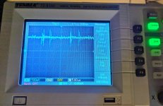
Do you have any resources on what to look for? I hooked up my scope but it just looks like garbage. I'm not at all familiar with testing video signals.
PXL_20240312_135634447~2.jpg IMG_20240312_090030~2.jpg
 
I'm using a single 64kb static ram board, no banking.


I did check every TTL logic chip with a chip tester before it went in the board, I don't think there are any duds in my case.


Do you have any resources on what to look for? I hooked up my scope but it just looks like garbage. I'm not at all familiar with testing video signals.
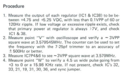
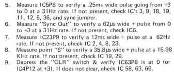
The Dazzler "1976 Rev C" manual has a very detailed diagnostic/troubleshooting section:
 
Well, going through the troubleshooting procedure.

2024-03-12 16_02_00-cromemco __ Cromemco Dazzler Instruction Manual RevC 1976 _ Free Download,...png
  1. Input & Output voltage output is good on both 7805's.
  2. At test point "V", I do NOT have a 3.5MHz signal here (it's measuring something like 62.5MHz but it's not even a square wave).
  3. However I do have a proper square wave here - 3.579MHz at IC7 P4&6.
  4. I do appear to have a ~16KHz rate on test point W.
There are more test procedures but I'm not going to go any further until I figure out what's up with #2. Just wanted to provide a status update. Should be able to take a closer look tonight.
 
That is helpful all the IC's were checked. Out of interest did you find any duds doing that, if so were they newer or vintage parts ?

You should be able to nail it with the troubleshooting procedure.
 
That is helpful all the IC's were checked. Out of interest did you find any duds doing that, if so were they newer or vintage parts?

Yes, got in probably close to 200 chips in total since many had to be ordered in minimum quantities. I tested all of them, and only found 2 bad 74175's out of all of them. I ordered a set of 5 from eBay - messaged the seller and hey graciously sent replacements which both tested OK. Many were NOS (date stamped late 70's-mid 80's). Some of chips I ordered from china which are HLF branded. They all tested good and have a '23 mfg date stamp so I guess they're still making those!
 
Well, going through the troubleshooting procedure.

View attachment 1275533
  1. Input & Output voltage output is good on both 7805's.
  2. At test point "V", I do NOT have a 3.5MHz signal here (it's measuring something like 62.5MHz but it's not even a square wave).
  3. However I do have a proper square wave here - 3.579MHz at IC7 P4&6.
  4. I do appear to have a ~16KHz rate on test point W.
There are more test procedures but I'm not going to go any further until I figure out what's up with #2. Just wanted to provide a status update. Should be able to take a closer look tonight.
You may just have a poor signal feeding your scope when attached to test point "V". What do you see with the probe on either of pins 1 and 2 of IC14, with scope ground attached to pin 7 of IC14 ?
 
You may just have a poor signal feeding your scope when attached to test point "V". What do you see with the probe on either of pins 1 and 2 of IC14, with scope ground attached to pin 7 of IC14 ?

Hi, just checked - so on IC14 p1&2 I am reading the 3.5MHz signal. Looking at the PCB though, "V" comes off pin 5 of IC14. On that pin, I'm measuring the 62.5Hz (I wrote MHz in the post above but meant Hz).

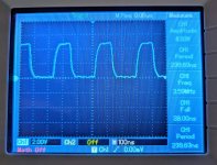
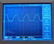
Here's a reading from IC7 P4:
PXL_20240313_003605333.NIGHT~2.jpg

This is the reading at IC14 P2:
PXL_20240313_003644722~2.jpg
 
Last edited:
Hi, just checked - so on IC14 p1&2 I am reading the 3.5MHz signal. Looking at the PCB though, "V" comes off pin 5 of IC14. On that pin, I'm measuring the 62.5Hz (I wrote MHz in the post above but meant Hz).

Here's a reading from IC7 P4:
View attachment 1275540

This is the reading at IC14 P2:
View attachment 1275541
According to the schematic, test point "V" should be connected to pin 3 of IC14 - it will be inverted from pins 1 and 2 of IC14. You measure 3.5MHz at pins 1 and 2 of IC14, which is correct. IC7 pins 4 and 6 will also be 3.5MHz, just successively phase shifted from the signal at pins 1 and 2 of IC14.
Pin 5 of IC14 is is the vertical sync signal - which you correctly measure as 62.5Hz.
Test point "W" is the horizontal sync signal - which you correctly measure as 16KHz.

Therefore... all the basic video timing signals on your board are present and correct.

Connect a 50 ohm resistor from the Dazzler video output to ground, and take a look at the signal across that resistor with the scope.
 
Last edited:
Weird I wonder what other discrepancies we'll discover?

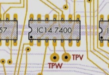
1710293387212.png

You can see in the foils TP V is on pin 5

I'll continue working through the troubleshooting steps
 
1710293660767.png

5. Measuring the same 62.5Hz here, maybe this is just worded strangely? If you follow the trace on this pin it also ends up at IC14P5 and TP "V".
6. Measuring 31.25Hz, as expected here... so maybe the above is wrong?
7. Measuring 62.5Hz, as expected
8. Measuring 16.03KHz, as expected
9. Measuring 4V at IC4P12, I think this is OK although I don't have a front panel or CLR switch

Unfortunately, it seems all of the other tests require a front panel which unfortunately I don't have. Maybe it'd be possible to emulate these actions through a development of a program? Or maybe it's time I built one such as http://www.s100computers.com/My System Pages/Mini FP Board/Mini FP Board.htm
 
Last edited:
Or not.. yikes! the switches alone would cost almost $200! Unless there are some cheaper alternatives out there?
I expect you should be able to accomplish the same things a front panel does, with use of most ROM-based system monitors.
 
You should be able to modify the test program as follows (all addresses and data values are in OCTAL):

Address: Data
0000: 076
0001: 200
0002: 323
0003: 016
0004: 076
0005: nnn
0006: 323
0007: 017
0010: 303
0011: 000
0012: 000

Change the byte at address 0005 to match the desired sense switch setting in the range 000 to 377.

An annoying feature of this test program is the requirement to hit RESET to change the value of nnn before executing it again at address 0.

It would be possible to modify the test program to read an octal value from the console and use that in place of the fixed constant at address 0005. Let me think about that one...

From a quick read of the article, step 15 will not be possible without the front panel.

There are a load of errors in the manual...

Dave
 
. Some of chips I ordered from china which are HLF branded. They all tested good and have a '23 mfg date stamp so I guess they're still making those!
I would be very cautious of those and not dare to use them myself. They could be any family of logic IC with the same pinout re-labelled, they could be cmos HC or HCT parts, or 74F etc etc. They may well have much shorter propagation delays than the original parts. Your IC tester can't pick this up.

One clue, when you do a scope recording of an output pin, if it is not a genuine 74 or 74LS TTL part and a cmos version instead, the output voltage swing will be close to 0 to 5V, where with the 74 TTL's the high voltage is in the range of 3.5 to 4V only (unless there is a pullup resistor) due to the nature of the output stage. One other way to tell is to measure the input pin current which is higher for plain 74 than 74LS and non existent for cmos in a static condition.

I'm pretty sure no semiconductor fab company is making new 74 series TTL. What it getting shipped are other new re-labelled parts I think deemed to be a generic replacement. Most of the time it is ok, it is just that sometimes it is not.

I'm not saying that these new parts won't work in the circuit in the Dazzler, they very well may do, it just throws in some uncertainty about timing errors.
 
Just thinking out of the box...

Why don't you just use RDOS commands directly? All you have to remember is that the test programs within the Dazzler manual are in OCTAL and require converting into HEX for use with the RDOS commands.

The first command in the test program (converted to an RDOS command) is:

O 80 0E

This turns ON the Dazzler and sets the base memory address to 0000.

The equivalent of the sense switch code (converted to an RDOS command) is:

O nn 0F

Where nn is the hexadecimal representation of the desired sense switch setting(s).

Use the SM command to modify the memory that is used by the Dazzler for display (starting at address 0000 as in the O 80 0E command above).

Note that RDOS is using some of the memory for workspace. So use the SM command sparingly. By default, addresses around 007C are used by RDOS. This can be changed by using the RDOS 'K 0F00' command to move the default stack and data area outside of the Dazzler screen address starting at address 0000. You can poke addresses 0000 upwards to your heart's content then without crashing the machine!

Enjoy...

Dave
 
Back
Top