• Please review our updated Terms and Rules here

PiDP-8/I

Hooray - We've got a second SLU as a real RS232 port

Hooray - We've got a second SLU as a real RS232 port

Today we are pretty well snowed in in the metro NYC area, which gave me time to get the second SLU added to the PiDP-8/i.

Jack, I ended up kludging together stuff that was easily available. The final suggestions of the gentlemen who responded earlier in the thread pointed me toward an FTDI FT232 based solution. I was really looking for only one more SLU, one for connecting a serial lineprinter, and so I went with something that gave me only one more SLU, however the approach can be expanded. The Microcenter has these Inland Products FT232 USB to RS232 adapters that are usually used for programming Arduino devices and I used one of those. So I have a USB cable plugged into the PI, going to the FT232 USB to RS232 adapter, and then a MAX232 connected to the FTDI adapter. That gets me to correct voltage level RS232.

In the PI, the bootscript needs to have a line added to tell SIMH what to do. The console is a KL8E, but if you want more SLUs, they will be KL8JA as device ttix. I only needed one more SLU, so to the bootscript I added:

attach ttix Line=0,Connect=/dev/ttyUSB0;300-8n1

Fortunately ttix looks like devices 40 through 47. I only needed 40/41, which is Line 0.

Under OS/8 on simh on the PiDP-8, I ran BUILD and LOADed and INSERTed the SLU2 handler. The KL8E handler can be compiled to make handlers for SLU2 and SLU3. I had already been through that exercise since on my real 8/e and 8/a, in addition to the console KL8E, I have a second KL8E at 40/41. So I already had an assembled SLU2.BN handler on the real machines. I copied it to RX01 and then read the RX01 on my PUTR PC that I have fitted with an 8" drive (so I can mount /RX01 /OS8 ). While under PUTR, I copied the SLU2.BN from the real floppy to an RK05 image that had BUILD that I would run on SIMH. [Did anyone notice that the default OS8.RK05 image with the PiDP-8 is missing BUILD? It seems to be David's diag-games-kermit.rk05 pack image.].

So with SLU2 added to the system head, and the hardware support attached in SIMH, I was able to COPY a text file out to SLU2 and it came out!! So now my PiDP-8 has two proper RS232 SLUs, one for the console terminal, and the other for the serial lineprinter (or Kermit, or whatever).

Tomorrow I will take a few photos, including the pen spring mod to the momentary front panel switches.

Lou
 
Last edited:
I would really like to see this pen spring mod. It's been mentioned a few times but I've never seen a real discussion exactly how to install the springs or source them in bulk.
 
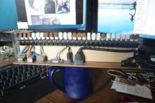
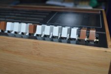
PiDP8I_Int_Bottom.jpgPiDP8I_Switch_springs.jpg

Rather than pen springs, I used the springs from Bic brand cigarette lighters (The ones under the button, rather than the long slender one that pushes the flint). For installation I first cut approximately 1/8" (3mm) from one end of the spring. Then, cut end first, I slipped them under the switch cap and up into the hollow space in the backside of the switch cap. Working the switch once seats them into the position they will want to sit, and seems to provide just enough pressure to keep the spring in place without glue while also returning the switch position reliably. This was easily done with the switches already assembled, so could be added to a finished kit easily.

As far as sourcing them, I have lots of friends that smoke, so asking for a round of dead lighters supplied me with plenty to disassemble for their springs.

Edit: Pictures are a little small here, but they can be found over on the PiDP google group in the 'PiDP Photo Thread'
 
And here is my photo of the pen springs fitted under the switch handles: http://www.vintage-computer.com/vcforum/album.php?albumid=328&attachmentid=29249

This is what the pens look like that were the donors: http://www.vintage-computer.com/vcforum/album.php?albumid=328&attachmentid=29247 . These are really cheap pens, that often come in a package of 5 for $1USD. One pen spring will make two switches momentary. I started by first cutting the spring in half with diagonal cutters, but ended up snipping a little more until I achieved the least amount of finger resistance that still returned the switch back to the normal state. This diameter of spring nicely fits in the hollow space up inside the switch cap. I did install the spring just as each switch was going on the skewer. I'm not sure how hard it would be to hold the spring compressed and try to slide it into place after the switch was already assembled on the skewer.

I did paint all my switches using NeXT's method and the paint he suggested. They came out great! I did the brown and also painted the white switches too.

The SLU2 is shown here: http://www.vintage-computer.com/vcforum/album.php?albumid=328&attachmentid=29248 . That works fine, and is cheap and easy.

Also, a few words about bamboo boxes as project boxes. I was thinking about making the emulated VR12 and started looking for bamboo boxes like the one that Oscar used. I found one distributed by Lipper International that appears to be made to imperial dimensions (a little wider and taller) and is a little shallower, but looks really close. The stackable boxes are nice in that they have a lip against which a front panel can rest. I saw boxes at the US retailer Bed, Bath, and Beyond that were also cute, but lacked the stacking lip feature. The BBB boxes come in a variety of sizes, including a small one that looked good for housing a PI by itself with some other hats.

Lou
 
Last edited:
I used the free TD bank pens. Take out the bottom spring, cut in half with clippers. Bend the cut piece to be safe and insert under the switch with the cut end into the switch. Works like a charm and you get 2 switches per pen.

I'm still assembling my unit. I just cut out the USB ports and tomorrow I hope to cut out for the hdmi. I will be using a serial with mine most of the time so I have to solder up a simple max232 setup to a perf board later this week.

I also copied the latest disk image onto a card. So hopefully everything works when I boot it up later this week.

Cheers,
Corey
 
Oscar, I sent You a Personal message awhile back, I hope that everything is OK..

Beg your pardon - I overlooked the PM Inbox! Yes, all good. Just completed another batch of PiDP-8s, now with the 'replica switches' that I had made. They turned out nicely, so if anyone is ever thinking of having custom switches made: Daier Electron of China seems to be a place you can trust :) (spoken as a client, nothing to do with them).

Regards,

Oscar.
 
Folks,

I finally finished the packaging of my PiDP-8/i today. My intent is to use it with a terminal, and so I wanted the RS232 level converter to fit inside the box. Similarly, I wanted a power switch and coaxial power input jack. Lastly, I wanted to bring the HDMI port out so that I can make the emulated VR12 someday. I did all this by hogging out most of the left side of the box and mounting the jacks in a thin aluminum plate. I also cut a clearance hole in the plate for the ethernet and USB ports of the Pi. It came out like this : http://www.vcfed.org/forum/album.php?albumid=328&attachmentid=31245 So, everything exits the left side. There are no other holes in the bamboo box (except the screws in the back to the wood blocks on the board.)

I had read about using magnets to hold the front panel on. I did not want to drill holes in the beautiful front panel, so I double stick taped magnets to the board and to the panel. There were two convenient spots that you can see in this picture. : http://www.vcfed.org/forum/album.php?albumid=328&attachmentid=31239 . The magnets were 3/4" square from a local arts and crafts store. They are not too strong, but not too weak. They hold the panel on just tightly enough to not make removing the panel difficult.

My finished setup is here: http://www.vcfed.org/forum/album.php?albumid=328&attachmentid=31242 There are some other photos in this album that showed how tight this all is inside the box. The left exit HDMI was a bit of a kludge, but works. Hopefully this can provide some ideas for others who haven't finished their assembly yet.

Lou
 
Nice! Now if only I could make time to put mine together.

Jack, I'm 80 miles north of Wilmette.

Matt
 
Hi All;

I have a Board, but NO Switches, When I first got my board from Oscar, I though I could get the switches at a later time..
Well, the 'new' switches according to Oscar won't fit the old board..
I am not sure what I can do at present time, any suggestions..
I was going to try and mate it to my PDP 8i clone/emulator board..
I have not heard from Oscar since about if He is going to do another Run of boards/switches..

THANK YOU Marty
 
Marty,

I would bet that a modification could be made to fit the new switches. They must be about the same width or else the front panel artwork would have had to change. Since only two pins on each switch are used, I would think the existing holes could be enlarged, or maybe the lower hole elongated. Some epoxy and a soldered on jumper for each switch could probably fix things up.

Lou
 
Hi All;

THANK YOU, Lou for the Suggestion/Idea, but until I can get Oscar's attention, and see if He has any Switches that He can sell me, this is a moot point..
I had been bugging Oscar since last October or so about getting some Switches, and it seems that I am very Low on the Priority List..
So, Thanks for You help..

THANK YOU Marty

"Bugging him" here is probably an ineffective strategy. Use the "proper" mail list: pidp-8@googlegroups.com

He's very-much listening there ... and it's quite a busy world :->!
 
Hi All;

I got the New Printed Circuit Board and the Switches, today..
Now to Re-look at the Video so I know what switches go where..
THANK YOU Oscar for the Switches and a Great board, and the layout..
Also, I have one of the Old Printed Circuit Board, if anyone is Interested in it..

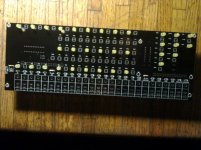
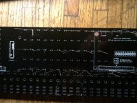
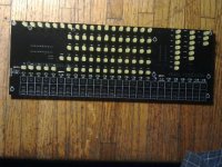
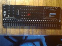
Here is some of my progress..

002.jpg 004.jpg

THANK YOU Marty
 
Last edited:
Hi All;

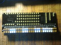
Here it is with all of the Switches in place, they have Not been Soldered in, as of yet, that will be sometime next week..

001.jpg


THANK YOU Marty
 
Back
Top