gerrydoire
Veteran Member
- Joined
- Aug 25, 2008
- Messages
- 1,145
here's some interesting news:
Pretty cool! we have cloned the acculogic card. Now I really feel sorry for all those chumps who buy $200 cards off ebay.
I paid $100 for mine

here's some interesting news:
Pretty cool! we have cloned the acculogic card. Now I really feel sorry for all those chumps who buy $200 cards off ebay.
What didn't work is the flash update program. Not sure what the reason is, but the eeprom when installed in the acculogic, is write protected. Any idea what that might be andrew? (I haven't looked at the datasheet yet)
here's some interesting news:
I received Bob Watts' Acculogic card in the mail the other day, and tonight I took the ROM off and put our EEPROM on it, and well, it just worked!
All I had to do was change the base address of where our BIOS is looking for the code. (it will auto-detect eventually)
So, that means, that for all of you acculogic users out there, you will soon have a new BIOS image that should let you break that 528MB barrier.
What didn't work is the flash update program. Not sure what the reason is, but the eeprom when installed in the acculogic, is write protected. Any idea what that might be andrew? (I haven't looked at the datasheet yet)
Pretty cool! we have cloned the acculogic card. Now I really feel sorry for all those chumps who buy $200 cards off ebay.
Yep, all 16bits of data is there. They are using the same latch mechanism as we are, even putting the 2nd data port at IOBASE+8. It all just worked.However, this seems rather suspicious to me. I can see the IDE control port working fine but the 16 bit data port is split between a HIGH and LOW port. Are you sure you are seeing all the data going to/from the drive and not losing the upper or lower byte along the way? If not then the Acculogic board is using a similar port configuration as the XT-IDE board and that is good news.
Yep, that makes sense. thanks to both you and john elliot for pointing that out. I'll scope out that line and see if it's a NC on the card. Probably is.I don't know for sure since I haven't seen the schematic but my first suspicion is that the Acculogic board probably does not include a *MEMW line to signal the EEPROM to do a memory write. If the board is designed to use a ROM then there would be no need for it. Check if pin 27 is connected to anything on the Acculogic ROM socket. Preferably its connected to pin 11 of the ISA bus.
PS, does the Acculogic board allow the use of DMA modes?
What didn't work is the flash update program. Not sure what the reason is, but the eeprom when installed in the acculogic, is write protected. Any idea what that might be andrew? (I haven't looked at the datasheet yet)
So what that means is that anyone with an acculogic card who would want to have flash upgrade ability would just need to add a single wire from ISA pin 11 to pin 27 on the ROM. easy enough. Otherwise, the andrew lynch ROM burning service might be of use.
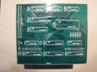
At the moment, both PCBs (first prototype run of 10) and some parts are racing their way toward me via UPS. I suspect I'll have everything by the end of next week. I'm then going to pack everything up and ship at least 1 set of everything to andrew for first assembly, and we'll see where that takes us.
With luck, we will having working PCBs and a combination of ICs that work solid and are readily available. Then I'll build up some more boards and those get distributed to testers.* Once it's been through the wringer a few times, we will then push the big button and get 100 cards made up and the madness begins! No ETA on the big order because we have no idea what sort of things will creep up in the beta phase.
stay tuned...
* Not sure how the testers scene is going to be handled yet:
1) each card is expensive. do testers buy them, and then forced to do work too? that's not really fair. do i just add the costs of these cards to the bulk order price per card to recoup?
2) hardware is in flux at the moment. how do we change parts on cards that have been scattered around the world?
3) are testers expected to able to solder to make mods? How about debugging code? We need testers who are able to get their hands dirty and say more than "xyz doesn't work" and help us find out why/where/how something may be at fault.
ideas and suggestions are welcome!
[snip]
* Not sure how the testers scene is going to be handled yet:
1) each card is expensive. do testers buy them, and then forced to do work too? that's not really fair. do i just add the costs of these cards to the bulk order price per card to recoup?
2) hardware is in flux at the moment. how do we change parts on cards that have been scattered around the world?
3) are testers expected to able to solder to make mods? How about debugging code? We need testers who are able to get their hands dirty and say more than "xyz doesn't work" and help us find out why/where/how something may be at fault.
ideas and suggestions are welcome!
Even a small electronics store should have one or two in stock. It may be best to do mailorder though - look for "test instruments". Good scopes are expensive so be careful that it can do what you want - especially frequency wise. There's a big difference in scopes. That said, if you don't have one, then any old used scope can be great to have, just be aware that many old ones are not worth more than 20 bucks. Someone into ham might be able to give you a junker. You'll learn a lot!per: Speaking for myself, where do you get oscilloscopes?
Even a small electronics store should have one or two in stock. It may be best to do mailorder though - look for "test instruments". Good scopes are expensive so be careful that it can do what you want - especially frequency wise. There's a big difference in scopes. That said, if you don't have one, then any old used scope can be great to have, just be aware that many old ones are not worth more than 20 bucks. Someone into ham might be able to give you a junker. You'll learn a lot!