• Please review our updated Terms and Rules here

A pair of Pets - Preparing to test after perhaps 40 years unused

That C59 is a 0.1uF surface mount capacitor that was put in a glass housing.

I am familiar with these, a while back I created a dead replica of a Rockwell pcb that used these capacitors, see photo. I had to source them, they were mil spec parts !

If you examine them under magnification you will find they are a surface mount monolithic ceramic style cap that has been repackaged into a glass housing.
 

Attachments

  • glasscap.jpg
    glasscap.jpg
    177.6 KB · Views: 10
Voltages directly from the transformer with nothing else attached, outputs numbered per my image below.

1 & 3 : 16.8 V
4 & 5 : 15.3 V
6 & 8 : 20.2 V

Do these seem correct? I haven't found the expected values yet in docs (looking now).

(I presume those are the pairs needed? I note that's the pairs they are used in to the 2x rectifiers and crt.)

Universalpet-PSU.jpg
 
That C59 is a 0.1uF surface mount capacitor that was put in a glass housing.
I originally thought they were diodes and so far haven't found a source for the exact type. I'm going to have to order them in either way so trying to find exact match on Digikey. Where did you get yours?

For ongoing troubleshooting - would it matter if I used a 0.1uF 25V ceramic radial? I have those to hand.
 
Last edited:
>>> edit: I've found C59, on the voltage regulation diagram. Looks like it sits directly on the +5V.

Exactly, which is what I stated in my post #16.

It is also the same for both types of boards you have.

C59 could have just died. Either that or there is something major wrong with that +5V rail. I am hoping the former!

The PET will work quite happily without C59 for debugging. What you need to find out is why it went...

Measure the voltage across it, but just give the power supply a quick ON and OFF. If the 5V regulator has gone short circuit you may have already done some damage somewhere.

This is the problem of trying to resurrect vintage computer equipment I am afraid.

Dave
 
I originally thought they were diodes and so far haven't found a source for the exact type. I'm going to have to order them in either way so trying to find exact match on Digikey. Where did you get yours?

For ongoing troubleshooting - would it matter if I used a 0.1uF 25V ceramic radial? I have those to hand.
You don't really need the glass ones, just replace it with a typical axial ceramic cap. I only used the glass ones because I was being fanatical trying to make an exact replica of a vintage pcb. (practically nobody else goes this far)


If you really want the glass ones, you can get them here:


Last edited:
Once I work this out, I'm going to get the glass ones too. I really want to try and get these machines back working and as original / unmangled as possible.

I figured I should run video next time I power it on:


I don't really have enough time (ie before more things burn) to start probing and measuring on the board. No point in turning it on again until I've done something different either I suppose.

Were those voltages at the transformer OK? If anything are they too low?

Here's C95 close up, I think it's the one burnt this time, C49 looks OK under magnifying glass. (still some dust there too, presume that can't be causing issues?)

002 - Copy.JPG

I just measured my mains voltage: 241.8 (and the back of the machine says ~240V)

The government site for my areas says:

"Australian standards require electricity to be supplied at 230 V
(+10% to -6%), therefore providing an allowable voltage supply
range between 253 V to 216 V. Voltage is generally supplied to NSW
users between 250 V and 240 V"

And finally, an observation of discolouration at CR2:

003.JPG

004.JPG
 
Last edited:
Don't look in the documents, you won't find the expected voltages!

I have a 'real' 8032 board and these are my readings:

You missed out the centre tap reading (black wire). 1, 2 and 3 form one supply with 4 and 5 a separate supply (and the monitor a third supply of course).

Black (2) to the browns (1) and (3) I get approximately 8 VAC. Brown to brown (1 to 3) I get approximately 16 VAC.

Across the blue wires (4 and 5) I get approximately 14.8 VAC.

Across the monitor wires (12" screen) I get approximately 19.8 VAC.

Your readings look somewhat similar. The blue leads are marginally higher than mine, but nothing to be too concerned about.

CR2 is the bridge rectifier for the +5V supply and, as a consequence, the heaviest loaded - hence it will be the hotter of the two (and the PCB will be slightly browner as a result).

So everything looks OK to me. But I would still checkout the centre-tap connection (2) by measuring the voltage from 1 to 2 and then 2 to 3.

Do that first and report back before moving forwards.

Dave
 
Sounds good. We are only talking of a small increase in voltage.

The issue with a transformer is generally that a winding goes open circuit. The slightly higher voltage is probably due to a slightly higher mains voltage.

I am having an early night tonight (I have to be up early tomorrow morning) so I will post the next step tomorrow.

You wouldn't happen to have a variac would you? A long shot, but I will ask the question anyhow...

Dave
 
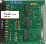
View attachment 1267417


The government site for my areas says:

"Australian standards require electricity to be supplied at 230 V
(+10% to -6%), therefore providing an allowable voltage supply
range between 253 V to 216 V. Voltage is generally supplied to NSW
users between 250 V and 240 V"
I live in QLD.

The line voltage here can get very high.

One of the reasons is our grid was designed to deliver energy, with a voltage drop along the line. But now energy is injected into it by solar installations. Their inverters are designed to cut off at 255V, but some people figure out how to reprogram that higher, so they can keep connected. In any case the regulation is degraded in that the voltage swings on the power grid have increased as well as many homes receiving around 250 at times when it is supposed to be 230v

This causes a lot of trouble, especially with American line transformers running via step-down transformers, because they were designed for 60Hz use and the peak core flux increases by a factor of 60/50 and if you run them from 120V , 60 HZ, in terms of peak core flux, this is as though you were running them from 120/110 x 60/50 x 110 = 144 volts in the USA, the cores saturate, they overheat and radiate large magnetic fields due to the high primary magnetization current. In many cases the primary should be run at around 95 to 100v on 50 Hz, if the secondary voltage remains high enough to get away with that.

Luckily though your PET transformer is designed for 50 and 60Hz operation, but the primary voltage, to help run the regulators cooler is probably better around 220 to 230V

The problem for my workshop at my home got so bad that I had installed a 15kW rated autotransformer, made by a Sydney company, to knock the entire house voltage down to 230V. This has multiple benefits for appliances, but certainly workshop gear and items with analog regulators in them. (I call it my Solar Defense transformer)

For my American vintage computers I run them via a variac too that generally feeds them with 95 to 100V. In one case I built an auto-regulating variac which cures the line voltage fluctuations, so I can set the running voltage just above where ripple breaks through to the output of the analog regulators. This means the computer (in this case a SOL-20) analog regulator's run as cool as possible.

Silicon Chip magazine did an article on it and they can supply the pcb:

here was my original article:

www.worldphaco.com/uploads/THE_CONSTANT_VOLTAGE_MACHINE.pdf

The best thing for you though, if you don't have one, is to feed your PET via a Variac to knock back the line voltage (some people put a bucking transformer in, I'm not fond of that).

Jaycar sell a well priced variac:


The procedure is you start with the variac around 1:1 wind it back until you see disturbances in the video (corresponding to ripple in the %v supply) then increase it by about 5 to 10V to allow for line fluctuations. With the 9" PET VDU, as soon as any ripple appears in the video, the raster scan bounces up and down because of the positive feedback around it. This can also be a symptom, even with normal line voltage, of the main capacitor losing capacitance.
 

Attachments

  • M2R.jpg
    M2R.jpg
    120.8 KB · Views: 4
Apart from running the PET on the lowest permissible line voltage, which helps run the 5V regulators as cool as possible, the only practical way to reduce the thermal dissipation in the bridge rectifier, that has overheated the pcb, is to move to Schottky types, these have a lower forward voltage drop than a standard Silicon rectifier and heat significantly less at the same current. Though it is harder to find schottky types in the inline bridge configuration, but easy as single diodes.

They have these at Mouser, but you would have to bend the leads a little to make them fit. Perhaps just replace the bridge that has cooked the pcb, the other one in the lower current path looks fine. No point in replacing it though with a standard silicon bridge as the heat won't change, though, if you got a standard bridge with a hole in it you could lift it a cm above the pcb surface and screw a heat fin to it, that would help a lot.

Probably a reasonable idea to limit the pcb damage to where it is. If a fiberglass pcb gets cooked enough, it starts to become conductive.

 
Last edited:
Well, if you are going to purchase a variac you can slowly increase the mains voltage to the PET and observe the DC voltage going into the voltage regulators and coming out of the voltage regulators.

Once you get to the specified output voltage (e.g. +5V for the +5V regulator) any increase in the AC supply from the variac (up to the nominal mains supply) should result in an increase in the DC voltage TO the voltage regulators but not FROM them. Any significant voltage increase FROM the voltage regulator (e.g. approaching +5.25V from the +5V regulators) would cause me to stop and checkout the regulator itself.

Increase the variac supply to the PET in steps and check the voltages into and out of all of the regulators at each step.

If you turn the AC supply onto the PET, and you have a faulty voltage regulator (e.g. it has gone short circuit and applies the full input voltage to the output) you have two scenarios:

1. One (or more) devices have gone short circuited and sacrificed themselves to protect the other devices.
2. You have done some significant damage that will keep you engaged for a while...

The +5V regulators are the main devices. Depending upon your particular PET you may have one or two of these. The +12V and -5V rails are generally used by the 4116 Dynamic RAM (DRAM) on the later PETs.

The variac way is the safest way...

Dave
 
The design of the TO-3 cased analog 5V regulators is such that they practically never fail in a manner where the output goes over voltage, to any significance. They have a voltage clamp in them. I have never seen one do it yet. I have heard of the occasional one going open, but not seen one do it myself. Though over many years the output voltage can drop just a little.

The other good thing about them is that they have good current overload and good thermal protection systems. If their output gets shorted out, they go into a low current limiting mode. In that condition they can get very hot though, because the entire input voltage is dropped across them and the power can be quite high even with the low current. If they lose their thermal coupling to the heat-sink, say if the coupling compound dries out or the screws/rivets come loose, they will go into shutdown mode because they overheat. Probably this is one reason why the pass transistor inside them practically never fails because the regulators protect themselves from the abnormal conditions which could melt the junction.

When National semiconductor designed the 5V TO-3 regulator, the original part being the LM309k, they said in their spec sheet they were "blowout proof". They were copied pretty well by most manufacturers, some made by Fairchild were "up-rated" with higher current specs on the internal pass transistor.

These regulators are wonderful parts and super reliable.

The capacitor you had fail was defective, not due to over voltage, it was a 50V rated part and the voltage across its terminal could never have been anywhere near that high without most everything else being vaporized. It is just one of those things that occasionally happens to a monolithic ceramic capacitor, out of the blue. It is rarer than a Tant capacitor failing like that, but I have seen it a few times now. It is not indicative of any power supply issue on your board.
 
Agreed.

I have a few examples at work where these "glass bombs" have gone bang! They just die due to natural causes...

Dave
 
Agreed.

I have a few examples at work where these "glass bombs" have gone bang! They just die due to natural causes...

Dave
It is interesting that there is a Dentistry version of the "Glass Bomb"

They call it the "Fluoride Bomb", and they fear it, and dream about it in the middle of the night and wake up in a cold sweat.

What happens is that Fluoride added to the water supply does a great job of hardening the tooth enamel. But, the Dentine can decay away under that hard shell. So they start drilling the tooth and the outer shell fractures (like Humpty Dumpty falling off a wall) to leave a mass of brown decay with no structural support, plus, apparently, it smells awful.
 
Last edited:
Loved learning about the Flouride Bomb! I've managed to leave work late the last 2 nights so avoided the opportunity for my quick purchase. I'm away for a few days now so it will be the weekend before I can continue.

In the meantime, is there a suggestion that I should try powering up again as these things are going to fail anyway? I'll hopefully pickup some non-glass replacements by then, even if I still intend to put in glass ones eventually.
 
Give it a go...

As Hugo stated, it is unlikely that a voltage regulator has gone input to output short circuit (although I do know of a very small number that have failed this way - but it is very, very small).

Even then, this would only account for a medium percentage of the capacitor's rated capability.

So, realistically, there is only a very small probability of further damage. I would certainly remove the old component though before trying.

Enjoy your time away.

I am just sorting through the remains of our old computer room before it goes to that great big skip in the sky. We are moving offices. Just found a bit of vintage gold amongst the cr*p, so it has made my day worthwhile!

Dave
 
I'm back, although still sans-variac.

I cleaned up the second failed capacity (I've now got C59 & C95 missing) and with my multimeter held to VCC on the CPU, powered on again.

got the beeps......nothing else fried......measuring a steady 5.14V.
After about 10 seconds I got the beeps again. Then again. 5.14 stays steady.

I presume I'm in a reset loop.

I haven't bought any 50V 0.1uf capacitors yet but have 25V, should I get them on in the meantime so it's a complete system to troubleshoot further?
 
No need. The machine will work fine without a few of them for now.

I would just check the /RESET pin on the CPU to rule out constant resets externally to the CPU.

It is then probably ROM, RAM or faulty sockets/decode logic.

Dave
 
Back
Top