• Please review our updated Terms and Rules here

AIM 65/40 repair

Joined
Nov 19, 2024
Messages
21
Location
Zürich, Switzerland
Hi all

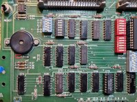
I picked this AIM up on eBay for "too cheap to say no" but it's a basket case. I repaired various things in the power supply like missing capacitors, wrong transistors, broken crystal...

The CPU was missing and I found three other broken logic ICs so far

20241128_195822.jpg --> 20241129_095824.jpg
I got it as far as the data bus reporting OK on the Fluke but there are still issues with the RAM

The RAM itself somehow survived, at least it can run in a ZX Spectrum just fine

20241129_100220.jpg
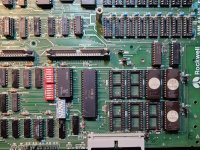
I think the problem is here somewhere, with these Motorola ICs eventually?

20250127_175557.jpg

20250210_231459.jpg

Any ideas how to pinpoint why RAM circuitry isn't working? I'm not familiar with AIM computers

Thanks in advance
 
Great selection then!

First off is to check all of the power supplies for the correct DC voltage and to make sure the ripple and noise are within sensible limits. Do you know how to do this using your oscilloscope?

Next is to check the clock signal.

After that is to check the reset signal.

Dave
 
The reason I am going back to basics is that I don't see any tests to indicate how we know the basics are actually working yet - before we start to look at the DRAM signal generation and DRAM address and refresh multiplexer operation.

I also didn't realise it was a AIM-65/40 machine...

Dave
 
You are right, the basics need to be checked

With the repairs done so far I can get as far as having a "BUS TEST OK" from the Fluke, the CPU gets a clock, reset and tries to do something

The voltages are

5.10 V / ~35 mV ripple at the source of the bench supply, but by the time it reaches the DRAM sockets it's at about 4.98 V / ~140 mV of ripple
-5.22 V / ~30 mV
12.5 V / ~100 mV

It does look a bit noisy. I'm also not sure if the voltage drop is normal. Without printer, display and keyboard it's at 1.2 A
 
Voltages seem OK on face value. The key thing is that +12V and -5V from the inverter circuit are present...

Clocks and reset?

You should observe a 16 MHz clock on Z43 pin 2 with divisions of two on pins 14, 13, 12 and 11.

Hopefully, you should have 1 MHz on the 6502 CPU pin 37.

The /RES signal should be observed on the 6502 CPU pin 40. This pin should go LOW when the <RESET> switch is operated and return HIGH when the <RESET> switch is released.

Can you then check the 6502 CPU pins 2 (RDY), 4 (/IRQ), 6 (/NMI), and 38 (SO). All these pins should (ideally) be HIGH.

Can you then check the 6502 CPU pin 7 (SYNC). This pin should be toggling HIGH.

Dave
 
Voltages seem OK on face value. The key thing is that +12V and -5V from the inverter circuit are present...

Clocks and reset?

You should observe a 16 MHz clock on Z43 pin 2 with divisions of two on pins 14, 13, 12 and 11.
All good
Hopefully, you should have 1 MHz on the 6502 CPU pin 37.

The /RES signal should be observed on the 6502 CPU pin 40. This pin should go LOW when the <RESET> switch is operated and return HIGH when the <RESET> switch is released.
Also good
Can you then check the 6502 CPU pins 2 (RDY), 4 (/IRQ), 6 (/NMI), and 38 (SO). All these pins should (ideally) be HIGH.

Can you then check the 6502 CPU pin 7 (SYNC). This pin should be toggling HIGH.
All good, except the /NMI has some interrupts on it (it's not permanently high)

Is a 65C02 CPU the right CPU?
For now it behaves the same with the Fluke 6502 Pod and the 65C02... I probably have an R6502 kicking around somewhere but I would have to open up other devices and check
 
So, if we have pulsing on CPU pin 7 (SYNC) then the CPU is executing instructions.

The question is - which ROMs are being selected.

Before we check this, however, can you photograph the link and switch settings please?

Z61 appears to be the address decoder (taking A12 through A15 and decoding the output into 16 blocks of 4K).

Can you check the output pins of Z61 to see which outputs are being activated?

Obviously the link/switch settings can confuse the CPU here if they are incorrectly set.

+1 for the ROM contents of course.

EDIT: It would also be interesting to see where the /NMI is coming from. I am not expecting this (unless something is errantly generating it).

Dave
 
Last edited:
ROMs:
Only three ROMs installed, one of them has differences (R32T3):
Diff:
Compare file
Address : (Buffer data)-(Chip data)
00000000h:(F2)-(F1)
00000542h:(0D)-(EA)
000008DFh:(0A)-(01)
000008EDh:(5A)-(5B)
00000AA1h:(E9)-(3E)
00000AA2h:(02)-(03)

The address decoder is falling apart. Input C looks terrible (squiggly line around 2 V)

The outputs aren't making proper contact

See attached pictures for board configuration... I tried following the manual here but there is a chance I missed something
 

Attachments

  • 20250211_171636.jpg
    20250211_171636.jpg
    1.3 MB · Views: 6
  • 20250211_171540.jpg
    20250211_171540.jpg
    1.3 MB · Views: 6
Thanks.

I have to go out shortly, so I will take a look tomorrow.

I suppose you could check the ROMs (pin 20) to look for activity...

Dave
 
R32T3-11 your ROM data.

The R32T3-12 ROM is on my /40.

I don't know the difference between -11 and -12 ROM. Maybe program a -12 ROM and see what happens.
 
Thanks for your so far. I will try to fix the dodgy address decoder and hope it's not broken.

The ROMs look OK but if we can rule out the decoder I can try to program a set.. just have to find a couple of 2532 if I even have any

EDIT: no ROMs get selected (pin 20 stays high)
 
Last edited:
So, if CPU pin 7 is pulsing, what is getting selected I wonder?

It is obviously 'escaping' from the ROMs...

Dave
 
Good morning

I've got this manual, but I'm having trouble finding the locations listed.

Random example, I'm trying to find page 2764 B0B1 = 20 22 F6

1739347252982.jpeg

There are two places with this sequence, but none match the notation B0B1

1739347326740.png
1739347418258.png

I also managed to fix some of the broken pins of the address decoder and replaced the socket. All inputs are looking like a pulse and there is now activity on pin 20 of the monitor ROM

Maybe I could plug the display back in and see if something is happening
 
>>> Random example,

Rather than picking a random location, why not look at the first few bytes to start with?

>>> Maybe I could plug the display back in and see if something is happening

Yep, give it a go. You may get lucky!

Dave
 
Back
Top