• Please review our updated Terms and Rules here

AIM-65 Video Output Success.

@Hugo Holden and @yogi63 I'm about to join the clu on the AIM-65 and I'd like to build myself a video board. Has there been any further development on this project over the last couple of years? Jörg are your gerbers still available? I'll probably layout my own board, but having a working example to start with could be useful.

Also, any better copies of the schematic than the rough PDF on the first page of this thread? It's not the easiest thing to read, though most of it is self explanatory.

Scott


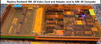
There was a booklet published by Rockwell on the RM-65 video card, which included the schematic. I could never find it, in the flesh, so I had to rely on the photocopies to compare it with the pcb tracks that I drew as a .jpg file from the very helpful images and X-Rays of an original board that @dfnr2 provided. By the way, without his dumps of the ROMs, this project would have been impossible, so he deserves the Lion's share of the credit for the project.

Has anyone ever helped you re-create a vintage pcb by providing X-Rays ? I don't think so, as Detective Monk might say, but @dfnr2 did, he did this, to help solve the mysteries in a 4 layer pcb. This was my first attempt at replicating a 4 layer pcb.

It was a very long road to create the replica pcbs.

But as noted, the conversion of the the .jpg files I made into Altium pcb files was done at my pcb maker. I could not use these files in any way to create Gerbers because I do not have Altium software and cannnot even open those files.

Interestingly, Altium has just been acquired by the Japanese company Renesas for 9 Billion dollars.

Jorg used my drawings to create Gerbers, I have not checked these against my pcb artwork, but I think likely they are excellent, so if you want to make an RM-65 video card, this is the way to go.

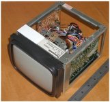
For my AIM-65 I configured into a base with an orange transparent acrylic top, to support the adapter & video card. Also with a copy of the software code on the base to activate it. But also I put this code into a ROM, to be able to quickly activate the card:


Attachments

  • 6545.jpg
    6545.jpg
    389.4 KB · Views: 8
  • AMRM3.jpg
    AMRM3.jpg
    55.6 KB · Views: 9
Last edited:
One of the places I was having trouble reading the schematic was the composite video output, pictured below. There's a couple of what look like Zeners (CR3 and CR4) on sync and video respectively, and I just can't read the part numbers of those two Zeners. Hugo, I see a number of resistors and diodes in that section of your board -- do you have the specifics? Thanks, Scott


.comp_output.jpg
 
Hi Sam,

I have successfully built the CRT board. I still have the Gerbers. If Hogo agrees, the Gerbers can be posted here.

Here's a better circuit diagram. You can also find some on Rich Cini's website.

best regards
Jörg
 

Attachments

  • Schematic CRT Controller.pdf
    5.3 MB · Views: 10
Thanks Jörg, that is a much cleaner diagram. So the two things I thought were Zeners were just 1N5817 schottky diodes. So I guess they're just stacking diodes to aim for a specific voltage drop?

I'm not sure I need the gerbers as I'm part way through laying out my own, which is going to be a little different from stock.

Scott
 
Thanks. I've got the cart a little ahead of the horse -- the computer has not yet arrived. Hopefully late this week or early next.

As soon as I get it and vet my assumptions about how/where I'm going to mount it, I ought to be ready to send off for the PCB.

Scott
 
Don't forget if you are using this with the AIM-65 you need to make the adapter board. It is quite hard to find the edge connector with right angle pins so that the adapter mates conveniently with the AIM. I found some with straight pins and improvised a metal tool to bend them at 90 degrees so that they look regular.
 
Yes, but with a little skill you can find a solution.
Mine looks like this (photo).
 

Attachments

  • AIM Stecker.jpg
    AIM Stecker.jpg
    300.3 KB · Views: 9
This is a standard 0.100 pitch edge card connector, or something wonky? I was thinking of just building myself a small backplane. Given that I only intend to install one board, inside the case, I was just going to replace the inverting buffers on the board with noninverting, and do away with the adapter. I'm also going to replace much of the bus decoding logic with a 22V10 PLD. It'll help a lot when the actual computer shows up (maybe as early tomorrow) and I have it sitting here in front of me, and I can see how to fit things.
 
Look at this: https://www.ebay.de/itm/404890408288
I think these should fit.

There have been many solutions in the past to connect hardware to the AIM. Also with CPU adapter boards. Many users prefer to keep everything original.
I am very excited about your solution. It's good to see something new and modern.
Yes, but it is all a little bit nasty.

It is better to find the connectors which had long Gold plated pins, for wire wrap assemblies , and simply make a spacer tool to bend them acurately at 90 degress, it gives a much nicer result. But I am prone to being a fuss pot. But I am not a software expert, but with hardware I might be.
 

Attachments

  • Con2.jpg
    Con2.jpg
    218.5 KB · Views: 5
Last edited:
The AIM-65 computer I bought arrived, and it's kind of an interesting piece. It came in this snazzy metal case:

1712286033474.png

The three switches on the front aren't connected, don't even have wires attached. There's also an IEEE-488 connector on the back, which has never been used, no wires ever soldered to it. The thing appears to be practically brand new. It's not even particularly dusty or dirty inside. Operation is a little bit intermittent -- sometimes it won't start. I think I want to put a scope on the oscillator or the reset circuit to have a look. There's video output jacks on the back that were never wired up either.

It's running a custom firmware called "Compute-A-Pleat" by "Repete Corp". It asks some questions:

Pair or Panel?
Size of Overlap?
Size of Return?
Width of Goods?
No of Widths?
Finished Width?

and then it either prints an I/O error, or prints something else out and restarts. I'm guessing by the error message that it's a custom BASIC program in ROM. I'll pull the ROMs at some point and build an adapter so I can read them.

"Repete Corp" is listed as a supplier of industrial automation controls, so perhaps this was some industrial controller. That the IEEE-488 connector was present but never wired up makes me wonder if this thing never actually received its final assembly and never got put to use.

Anyhow, once I resolve the problem with intermittent startup, it seems a perfect platform to develop a video board for. Hopefully you can see now why I want to design the video board so it fits inside the case, rather than have an adapter and video board sticking out the back of the case.

Scott
 
That is a very interesting case, looks very nice I think. And there would be plenty of room to fit a video card in it and you could even add a small CRT VDU (5" or 6") on the top of the case, toward the R hand side. You could create a stylish housing for it, reminiscent of a smaller version of the 9" PET VDU enclosure to capture that 1970's computer look.
 
If you wanted, I could supply you with a really beautiful vintage NOS Panasonic 5.5" diagonal face industrial open frame CRT VDU. I have two versions, one with a white and one with a green phosphor CRT. The white one is rarer than the green. I acquired these some years ago and have had them in storage. They are excellent high resolution small CRT VDU's and are great for computer text/graphics, like those out of the RM-65 card. They are powered from a 12V @ 0.7A capable supply. You would have to PM me if you were interested in buying one. I only have a limited number left now. CRT vdu's, especially NOS ones are getting rarer now. Attached a photo of one, sorry about the image blur.
 

Attachments

  • vdu.jpg
    vdu.jpg
    145.1 KB · Views: 9
Last edited:
@smbaker: At the VCF Southwest last summer, I picked up an AIM-65 with the same case as yours. Mine had an internal backplane with four slots in a 2x2 arrangement, and a buffer board to interface the expansion bus to the backplane. The backplane supports 44-pin connectors, and doesn't appear compatible with either the AIM-65 expansion bus or the RM-65 bus. The slots are farily deep and could accommodate an RM-65 card (such as the video card) and an adapter. If you have the same bus, you may be able to make adapter cards for AIM/KIM/SYM expansion boards and for the RM-65 bus. It's possible these are custom units and all have different innards. I'd be interested to see what's inside yours.
 
Thinking about Hugo's monitor... Discussing over PM... :)

dfnr2: My case has pretty much nothing in it except the AIM65 board itself. I have designed a small backplane to fit inside and a video board. We'll see how it goes. I did break and list the customer software that is installed in it -- it did pretty much nothing other than calculations. No IO other than a couple pokes to turn the printer on and off.

I also burned the glitchworks diagnostic ROM and used it to verify that my board is at least mostly working right. I think I ran the tests about a dozen times, all were flawless except one that encountered a RIOT RAM error. Probably going to run it a dozen more, and if the RIOT RAM error doesn't recur, just consider it a glitch. The other ROMs installed in mine were stock basic, and stock monitor (with two bytes changed to make it auto-run the BASIC program).
 
I am also new to the AIM-65 and would be interested in the Gerbers, if you are both willing to share.

I can start a separate thread if preferred, but I just purchased an RM65-7102E GPIB controller on eBay, and I would be willing to undergo a similar recreation process if there is any interest. I have searched for the manual, but cannot seem to locate it anywhere. Does anybody have any tips to locate a scan or physical copy?
 
@Hugo Holden and @yogi63 I just finished soldering up my board and I realized .... I don't have a copy of the ROMs anywhere? I could use both the character generator ROM and the program ROM. Do you happen to have a copy I can use?

Thanks,
Scott
 
Back
Top