• Please review our updated Terms and Rules here

Another 8032 to fix!

KevinO

Experienced Member
Joined
Apr 13, 2012
Messages
380
Location
Des Moines, IA USA
I sold my spare working 8032 at VCF Midwest last week, so I pulled this one out of mothballs (or should I say 'mouse nests') to get it going.

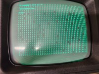
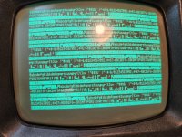
Had some chips in the wrong places, but got that sorted, and now I get this screen. Ah, this is obviously bad video RAM, so I replaced the 4 2114 ICs, and...same thing! Hmm...

PETTESTER seems to indicate bit 3 is stuck low? Does that look right to you folks? Where to poke next? I can use a scope, but I'm pretty much a hack. Any ideas to get me on the right track?
 

Attachments

  • 20230920_220851.jpg
    20230920_220851.jpg
    3.4 MB · Views: 15
  • 20230920_214744.jpg
    20230920_214744.jpg
    4.3 MB · Views: 15
In my effort to post before going to bed last night, I forgot to mention a few things. I DO get a startup chirp, and I can definitely type on the keyboard. Typing 'catalog' results in 'ka\aloo', and the garbled equivalent of 'syntax error' which seems to me to suggest bit 3 is flipping, rather than just stuck high or low.

I have Tynemouth's PET ROM/RAM device, and switching out the ROM and RAM makes no difference! So...a logic chip somewhere, perhaps?

I also just realized that mine is one of several PET threads going on. As such, I would like to see others get theirs fixed first! Mine is by no means urgent. I enjoy working on these, but need a little hand holding to point me in the right direction.
 
Last edited:
It doesn't always have to be bad video RAM...

It could be a faulty data bus buffer. I think there are two (2) sets of data bus buffers in series between the CPU and video RAM, so these can be faulty in a variety of combinations.

I am out at the moment, but I will have a look at the patterns when I get back.

As this is an 80 column PET, you have odd and even video RAM to contend with, so treat each alternate byte as unique and look at the patterns independently.

Dave
 
You are 100% correct about my PETTESTER identifying data bit 3 stuck low :)...

On the basis that you have exchanged UC4 for a good 2114 RAM device then it must be UB4.

Your problem appears to be limited to the EVEN VRAM and data bit 3 - which is UC4 (assuming I have found the correct schematics for your machine).

If it is not the RAM, then it must be the D3 data bit supported by the UB4 '244 data buffer.

It can't be the data bus buffer closer to the CPU, as this would result in faults in both the ODD and EVEN VRAM.

Dave
 
Thanks Dave! I'm not 100% confident about the status of my replacement 2114s, but moving them around doesn't change anything, so I think it's good. So that leads me to UB4. Sadly, being in the US, I'm currently at work for another 5 hours, so I'll get to it tonight and report back. Sounds like you've got the right schematic....here's the one I'm working from: http://www.zimmers.net/anonftp/pub/cbm/schematics/computers/pet/8032/8032029-08.gif

As always, your help is very much appreciated.
 
No problem.

I assume you installed sockets when you replaced the video RAM?

Just thinking ahead...

Dave
 
No problem.

I assume you installed sockets when you replaced the video RAM?
Absolutely! I'm tempted to pull the socket and make sure I didn't mess anything up. I'm usually pretty confident, but I also did the CPU socket (wouldn't work after the RAM/ROM board was inserted, and I lifted a pad on the CPU socket, so now I'm questioning my earlier work. (On the CPU socket, those white sockets are a b*tch. Part of the contact lays on TOP of the board, and you sometimes can't get it unstuck.)
 
Absolutely! I'm tempted to pull the socket and make sure I didn't mess anything up. I'm usually pretty confident, but I also did the CPU socket (wouldn't work after the RAM/ROM board was inserted, and I lifted a pad on the CPU socket, so now I'm questioning my earlier work. (On the CPU socket, those white sockets are a b*tch. Part of the contact lays on TOP of the board, and you sometimes can't get it unstuck.)

They are not really a B*tch, if you understand them & take the time to test them. (it sounds like a remark from Women's Lib)

Those white sockets are known as single wipe types, because, when the IC pin goes into the socket, the metal claw on the socket only presses up against one flat face of the IC pin. Regrettably, the other face of the IC pin presses against plastic.

On the other hand, "dual wipe" sockets, have have a claw system that presses up against both of the flat faces of the IC pin. Improving the chances of a good connection.

Still, in the case of the single wipe white socket, they can still be ok of the IC pins on their outer surfaces are clean.

I have a PET still with single wipe original sockets & it is ok.

But, I have checked each socket receptacle, with a pin taken from a defunct IC and soldered to a small wire handle, so that I could confirm that each socket hole has a reasonable physical tension against the IC pin.

If any adapters with a geometry of a pin, that is greater than a typical IC pin is plugged in (and this applied to all IC sockets single wipe, dual wipe, machined pin, then unfortunately these is a loss of physical tension when a genuine IC pin is plugged into the socket later and poor connections result.

One interesting curio about the white single wipe IC sockets in the PET, is that you can lift off the plastic shroud. Then you have access to each socket, pin 1 by one if you need to replace them or remove them and fit a dual wipe socket instead.
 
Last edited:
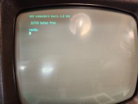
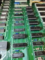
@daver2 , you called it again! The LS244 at UB4 fixed it. I'm not sure I understand how that LS244 buffer works I could clearly see a changing signal coming in and coming out of the pins corresponding to bit 3, where what I was expecting to see was no signal. Regardless, that was the fix. Oh and I didn't have an LS244, but I had an HCT244 that works fine. That was an easy one, relatively speaking. Thanks again for your help! Still have to check cassette and IEEE operation, of course.

I may plug that old IC back in and compare signals and see if I can see what's happening on the scope.
 

Attachments

  • 20230921_213623.jpg
    20230921_213623.jpg
    1.8 MB · Views: 7
  • 20230921_213557.jpg
    20230921_213557.jpg
    2.2 MB · Views: 7
I do my best! Another one resurrected.

You must remember that a 244 buffer is bidirectional - meaning it is used both in read and write mode. Different gates are used internally - so you may get confused if the chip is 'half working'.

There are two separate active LOW enables - one for READ and the other for WRITE.

You could use a 2 channel scope and look at the signals only when the appropriate enable is LOW. This should identify which 'half' of the chip is broken - as you should find that one (or more) data lines are then stuck (low or high) when looking only at the correct time.

Try it with the old chip to see...

Dave
 
@daver2 , I finally got around to plugging in that 244 at UB4. I ended up comparing the output of pin 9 from the bad IC to the good one. While I had seen what I thought was a 'good' signal on the bad IC, when comparing the two, it turns out they are inverted! So that's what was broken on the original IC. While I admit I don't understand how the LS244 works, especially how it's wired in this circuit, it appears to me that the output was supposed to be inverted when it wasn't, or vice versa. But I needed to compare it to the working one to see the difference.
 
The way to think of it is as follows:

1695643687845.png

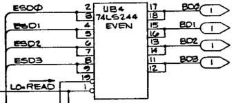
When pin 1 is LOW (/READ), the CPU is performing a READ from the video RAM and the data present on ESDn is transmited onto BDn.

When pin 19 is LOW (/WRITE), the CPU is performing a WRITE to the video RAM and the data present on BDn is transmitted onto ESDn.

When both pins 1 and 19 are HIGH, the buffer UB4 is disabled and no data flows between the ESDn and BDn busses.

If pins 1 and 19 are both LOW at the same time, we have a problem - as data is trying to flow in both directions - and we end up with a complete and utter mess!

Trigger the oscilloscope on pin 1 being LOW (/READ) and then look at the signals present on ESD0 and BD0. Whatever is present on ESD0 should appear (unmodified) on BD0 (but ONLY when pin 1 is LOW). Repeat for the other signals n=1, 2 and 3.

Trigger the oscilloscope on pin 19 being LOW (/WRITE) and then look at the signals present on ESD0 and BD0 again. This time, whatever is present on BD0 should appear (unmodified) on ESD0 (but only when pin 19 is LOW). Repeat for the other signals n=1, 2 and 3.

The SN74LS244 is a non-inverting buffer so the output should equal the input (when the buffers are enabled).

Dave
 
Back
Top