• Please review our updated Terms and Rules here

Apple IIe + Softcard : IN and OUT Z80 statements

Wawavoun

Experienced Member
Joined
May 17, 2020
Messages
53
Location
Alsace Yo !
Hello,

My question is almost in the subject.

I want to run some assembly code on a Z80 located in a Microsoft Softcard.

This code include IN and OUT statement followed by a 8 bits address. I believe these instructions use the lower byte of the address bus and the ioreq pin of the Z80 to say to the hardware that this operation do not involve the memory but some special io devices.

On the Microsoft Softcard a quick look at the schematic show the ioreq pin is not wired... So I think IN and OUT instructions has no chance to work. Can you confirm ?

Second : what is the best way to modify the code ?

I think I can use LDA/STA at the right address in place. Will this be correct ?

Thanks for your advices and help.

Regards.
Philippe
 
There is no such thing as "right address" in this case. You have to go deeper and figure out what the code in question is accessing and requiring in the I/O address space in the first place.
 
Forgot about this code. I do more simple tests... Just "by hand" write and read into the FPU board.

I can access (either with the monitor or in Applesoft Basic with poke and peek) to the command / status register and to the in/out top data into the stack.
In slot 1 I use $E090 (data) and $E091(command/status) as addresses.

I found an address translation table from 6502 to Z80 and this should become $C090 and $C091 in Z80 mode.

Alas these addresses does not work...
 
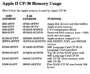
You have your addresses backwards: $C090 and $C091 are memory mapped I/O addresses in the 6502 which are mapped to E090H and E091H in the SoftCard's Z-80 address space.
 
Your are right.

I cross the addresses but just in the above message...

During the test I use the correct values and I confirm that
In 6502 mode : I can push $1A into $C091 then $C090 give the good result (pi in ieee notation).
In Z80 mode : I also push $1A into $E091 and then E$090 give nothing (4 time zeros) into Z80 mode.

Regards.
Philippe
 
What are the state of the 4 DIP switches on your Soft Card? S1-1 can enable/disable the address translation.

How are you performing your testing within the Z80 environment? Can you give us an example of how you are doing it please?

If you also look at the schematic you will also observe that the /MREQ signal is not connected either! This implies (to me) that only the Z80 address bus and the /RD and /WR signals are used. As a result, the Z80 I/O instructions will do something (in my opinion). You should also note that the high byte of the address bus is also used - even with an 8-bit I/O instruction.

If you are trying to port Z80 assembler software designed for another machine over to the Z80 Soft Card, then you will have to look in detail about what is being done. I/O instructions (on a Z80) usually manipulate I/O devices - and these devices may not (almost certainly will not) be present on the Soft Card. This (as previously mentioned) will require a much more in-depth analysis of the existing software and to understand exactly what it is trying to achieve - rather than just substituting (say) an IN instruction for a LD instruction...

Dave
 
Last edited:
All the bottom side (edge connector side) buttons of the switches are down so according to the manual seems to be off.

I do the Z80 tests with Microsoft GBasic into CPM 2.23.
Basically :
first "POKE &HE091, &H1A"
then 4 times "PEEK &HE090" to get the 4 top bytes of the stack.

At this moment porting a code to the Softcard is not my main concern. I should first succeed to 'talk' to the FPU board from CPM.

Regards.
Philippe
 
Last edited:
OK,

So switch settings look good and so does your test program...

Let me think a bit more...

Dave
 
What part number is your FPU board - and can you point me to the manual for it online please?

A couple of thoughts:

1. Can you do some peeking from 'known' I/O space in the 6502 (e.g. from the iie 5 1/4" disk controller card).

2. Can you do some peeking and poking to memory to see whether that works correctly or not?

Dave
 
Thanks for your help.

The board is a rebuild of CCS APU 7811. The manual is here joined.

Yes I can try to poke and peek in 'normal' memory addresses.
I can do this test this evening but I have to find a suitable address to do so... $0100 to $93FF seems to be normally free under CPM.

1680607999165.png

You mean access to know good 6502 addresses but from CPM ?
If found here https://6502disassembly.com/a2-rom/C600ROM.html what is, I think, the rom content of the floppy controller. This one stay at $C600 ? Right ?
I will give a try to read these addresses this evening from 6502 and then from CPM.

Regards.
Philippe
 

Attachments

  • CCS Apple II APU 7811 Owners Manual.PDF
    989.2 KB · Views: 7
Are you running this code in BASIC as a program or hand typing? BASIC on the Z-80 may run faster than AppleSoft in this case and read the return values before they're ready. Just a thought. For fun, try:

10 A = PEEK(&HE030)
20 GOTO 10

You should hear a faint whine from the speaker.
 
Thanks for the manual.

I had to do an important job at work... Just waiting for a response back from someone now.

Yes, bit 7 of the status register is a BUSY bit. if this bit is SET, then the arithmetic processor is still busy doing what you asked it to do...

Yes, reading some data bytes out of the floppy ROM might be a good start.

Failing that, just read and display the first few data bytes from Z80 memory address 0x0000 to 0x0010.

Address 5 should be a jump (0xC3) into the CP/M BDOS.

Dave
 
I do the test.

Under CPM and GBasic I can peek without problem starting from $E600 to $E60F and the values are ok with the floppy controller rom listing.
So basically peek works and address translation also.

Now as soon as I try to read into the FPU board this evening some strange things happen. I have not see that yesterday.

Sometime GBasic and CPM definitively hang (mainly if I do the peek in direct mode) and sometime (usually with peek into program mode) I got a "syntax error".
I check several times and there is no syntax differences between the two trials so I assume something goes wrong during execution of the program...
It is not a problem of AM9511 response time, in direct mode there is enough time between the command poke and the peek read.

Poke always works but of course for the FPU address verifying is not easy (there is no way to read again the command sent).
If I try to read the status byte CPM and GBasic did hang and become crazy with strange colors on the screen and B drive starting alone without disk inside...
I have to make a power down to get the computer working again, With a ctrl+pomme+reset CPM restart but the screen keep his strange colors.

I start to think that something in the bus timing of the Softcard is not compatible with this FPU board. Bad surprise...
 
Here is an 'odd' thought.

Is it possible that GWBASIC under CP/M is actually attempting to actually use the FPU itself?

Dave
 
I cant see how this could be possible ???

I do more check yesterday and I can confirm that the board works very well in 6502 mode.
I not only do a simple push pi but several successive operations into a basic program with a full success.

I will give a last try from CPM with a different tool than GBasic (for example DDT) and see but if this does not works also then...

I have a scope, a logic analyser etc... so I am ready to go deeply into the bus signal and try to see timing differences between an access to the board in 6502 mode and in Z80 mode.
What could be helpful is documentation about all these electrical signals. Can I find this somewhere ?

Thanks and regards.
Philippe
 
The schematic for the FPU board itself is relatively simple.

I would be able to help you instrument up the FPU board with a logic analyser - and we should be able to see the COMMAND and RESULTS bytes that are transferred.

Dave
 
Okay, great thanks.

I have only 8 ways on my logic analyzer.
I will probably made some read and write records of the data bus (D0 to D6) on AM9511 pins with the relevant clock first into 6502 mode.

On your opinion what should I use as clock reference : phi0, phi1, Q3 ?

Philippe
 
OK, 8 channels is a bit more limiting - but it can still be done...

I would monitor 4 data lines (either high or low nibble), /RD, /WR, C/D and the trigger clock.

I would use the clock on the AM9511 - which is the inverted Q3 clock.

Writing your 1A should result in seeing a consistent '1' (if monitoring the high nibble) and a consistent 'A' (if monitoring the low nibble).

Dave
 
I think I may have found your issue.

On the AM9511 device there is a /PAUSE output pin. This pin goes low to signify that the CPU should extend the bus cycle to permit the AM9511 to 'catch up'. This /PAUSE signal does not seem significant for a read cycle, but seems appreciable for a write cycle.

The /PAUSE pin goes through a bit of TTL logic to become the RDY signal on the bus (pin 21). I guess (without checking) that this will hold up the 6502 cycle until the AM9511 is ready.

Looking at the schematic for the Z80 SOFT CARD, pin 21 (RDY) is also an output (and not an input)...

The equivalent /WAIT pin on the Z80 CPU appears to control whether or not the Z80 is actually running.

I therefore suspect a major inconsistency between the operation of the Z80 SOFT CARD and devices operating RDY. Surely not though?!

OK, that is what I am suspecting - but you have the hardware and the logic analyser to check for real...

Dave
 
In the same time this afternoon I give a close look to the FPU board and Microsoft Z80 board schematics and go to exactly the same conclusion... Arf !
 
Back
Top