• Please review our updated Terms and Rules here

Build your own PDP 8I, Part 3..

So much for 'a bit of light relief'!

I have left my schematics at home again - so I will have to have a look when I finish work and get back to you.

I would have thought that this bit was going to be easy - but (once again) we are trying something new within your creation so there is always the chance that we will find something wrong.

Dave
 
Hi All;

Dave, I went to slow mode and then to Single step..

0000 6000 IOF - Make sure E14 pin 9 is still '0'.

F0,
F1,
F2,
F3,
A4,
CP0-7..

0001 6000 IOF - Make sure E14 pin 9 is still '0'.

F0,
F1,
F2,
F3,
A4,
CP0-7..

0002 6001 ION - Make sure E14 pin 9 becomes a '1'.

F0,
F1,
F2,
F3,
A4,
CP0-7..

0003 6001 ION - Make sure E14 pin 9 is still a '1'.

F0,
F1,
F2,
A3,
F1,
F2,
F3,
A4,
CP0-7..

0004 6000 IOF - Make sure E14 pin 9 becomes '0'.
0005 6001 ION - Make sure E14 pin 9 becomes a '1'.

F0,
F1,
F2,
A3,
F1,
F2,
F3,
A4,
CP0-7..

0006 6000 IOF - Make sure E14 pin 9 becomes a '0'.
0007 6001 ION - Make sure E14 pin 9 becomes a '1'.

F0,
F1,
F2,
A3,
F1,
F2,
F3,
A4,
CP0-7..

THANK YOU Marty
 
Very interesting - good detective work. Sherlock Holmes would be proud of you!

I will have a look at what that means when I get back home.

Dave
 
Ahhhhh!

This behaviour may be correct!

I forgot that interrupts are only enabled after executing the NEXT instruction (to permit an ION within an interrupt handler followed by a 'return from interrupt handler' instruction (JMP I XXX)).

The test program may be executing the following IOF before actually enabling the interrupt and then clearing it (if that makes sense). I will double check when I get home and re-issue my test program if this is the case (which I think it is).

Never mind - we inadvertantly tested another branch in the state machine...

Dave
 
Hi All;

Dave, I was thinking the Same thing.. But, Your the Software aficionado..

"" Ahhhhh!

This behaviour may be correct! ""


THANK YOU Marty
 
Try this program instead...

STOP CLEAR

PC=0000 AC=1234

SINGLE STEP the following program:

0000 6000 IOF
0001 6000 IOF
0002 6001 ION
0003 7000 NOP
0004 6001 ION
0005 7000 NOP
0006 6000 IOF
0007 6001 ION
0010 7000 NOP
0011 6000 IOF
0012 6001 ION
0013 7000 NOP
0014 7402 HLT

Where there is an IOF - E14 pin 9 should become '0' immediately after executing the instruction.

Where there is an ION - E14 pin 9 should become a '1' immediately after executing the instruction - but the following NOP will also be executed as part of the single step process.

If E19 pin 9 is a '0' when an IOF instruction is executed - E19 pin 9 should remain a '0' at the conclusion of the instruction.

If E19 pin 9 is a '1' when an ION instruction is executed - E19 pin 9 should remain a '1' at the conclusion of the instruction (plus the following instruction).

AC should not change from 1234.

At the conclusion of the test E19 pin 9 should be a '1'.

Press CLEAR. E19 pin 9 should become '0'.

We all make mistakes sometime...

Dave
 
Hi All;

Dave, Thank You for the Program Update..

"" We all make mistakes sometime... ""
Based on what we have found on this Board, I am WAY Ahead of You on this regard..

"" Try this program instead...

STOP CLEAR

PC=0000 AC=1234

SINGLE STEP the following program:

0000 6000 IOF
0001 6000 IOF
0002 6001 ION
0003 7000 NOP
0004 6001 ION
0005 7000 NOP
0006 6000 IOF
0007 6001 ION
0010 7000 NOP
0011 6000 IOF
0012 6001 ION
0013 7000 NOP
0014 7402 HLT
YES !!!!!
Where there is an IOF - E14 pin 9 should become '0' immediately after executing the instruction.

Where there is an ION - E14 pin 9 should become a '1' immediately after executing the instruction - but the following NOP will also be executed as part of the single step process.

If E19 pin 9 is a '0' when an IOF instruction is executed - E19 pin 9 should remain a '0' at the conclusion of the instruction.

If E19 pin 9 is a '1' when an ION instruction is executed - E19 pin 9 should remain a '1' at the conclusion of the instruction (plus the following instruction).

AC should not change from 1234.
YES..
At the conclusion of the test E19 pin 9 should be a '1'.

Press CLEAR. E19 pin 9 should become '0'. ""
YES..

THANK YOU Marty
 
Great news.

Let's repeat some of the basic instructions (just in case we have convinced ourselves that everything works when it doesn't) and then I will concentrate on the addressing modes. I think we will need the additional memory adding though to make the tests meaningful. I don't seem to be able to get any meaningful tests with only 16 words of memory (we may end up kidding ourselves).

AND/DCA test (partial TAD):

PC=0000 AC=7777

0000 7200 CLA
0001 1010 TAD 10
0002 0011 AND 11
0003 3012 DCA 12
0004 1013 TAD 13
0005 0014 AND 14
0006 3015 DCA 15
0007 7402 HLT
0010 0770 - Constant.
0011 0707 - Constant.
0012 0000 - Should contain the value 0700 after running the test.
0013 7007 - Constant.
0014 7070 - Constant.
0015 0000 - Should contain the value 7000 after running the test.
0016 0000 - Unused.
0017 0000 - Unused.

Dave
 
Hi All;

Thank You Dave for the Next set of tests..
I have a few errands to do, But I will run the test after I get back here, and report back to You..

"" I think we will need the additional memory adding though to make the tests meaningful. I don't seem to be able to get any meaningful tests with only 16 words of memory (we may end up kidding ourselves). ""
I think these Tests are Great !!!!
And I think Usefull, to someone with a Real 8, with very limited Memory, these Test would be Invaluable.. Just to see something functioning in their Machine..

There is a Problem !!

"" AND/DCA test (partial TAD):

PC=0000 AC=7777

0000 7200 CLA
MA '0000,
Mem '7200
MB '0000
PC '0001
IR '7200
AC '0000..

0001 1010 TAD 10
MA '0010,
Mem '0770
MB '0770
PC '0002
IR '1010
AC '0770..

0002 0011 AND 11
MA '0011,
Mem '0707
MB '0707
PC '0003
IR '0011
AC '0700..

0003 3012 DCA 12
MA '0012,
Mem '0700
MB '0700
PC '0700
IR '3012
AC '0000..

0004 1013 TAD 13
MA '0300,
Mem '7200
MB '0700
PC '0701
IR '7200
AC '0000..
0005 0014 AND 14
0006 3015 DCA 15
0007 7402 HLT
0010 0770 - Constant.
0011 0707 - Constant.
0012 0000 - Should contain the value 0700 after running the test.
YES, '0700
0013 7007 - Constant.
0014 7070 - Constant.
0015 0000 - Should contain the value 7000 after running the test.
No, '0000
0016 0000 - Unused.
0017 0000 - Unused. ""


THANK YOU Marty
 
Last edited:
That's unexpected...

For some reason MA has got screwed up.

Can you tell me what Fx and Ax cycles were running for the preceding instruction (0003 3012 DCA 12) and for the one in error (0004 1013 TAD 13) please.

It looks like PC has got loaded with 0700 as a result of the DCA 12 and disappeared off to infinity (well, back to the instruction at 0000 - which is CLA).

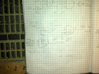
Can you just double check that DCA is included in the logic equation feeding J7 pin 4 on schematic LD11 please. It should be MIC+IOT+DIRECT*(JMP+JMS+DCA) and the state machine should go F0, F1, F2, F3 and end with A4 for the DCA 12.

Is it possible that PC(L) is being triggered as a result of executing the DCA somewhere?

I am just trying to come up with a number of scenarios that would load the PC at some inopportune point.

Dave
 
Last edited:
Hi All;

Dave, Thanks for the Scenarios, I will be getting to them late tomorrow morning..

"" That's unexpected...

For some reason MA has got screwed up.

Can you tell me what Fx and Ax cycles were running for the preceding instruction (0003 3012 DCA 12) and for the one in error (0004 1013 TAD 13) please.
YES .. Tomorrow, I will see and let You know..
It looks like PC has got loaded with 0700 as a result of the DCA 12 and disappeared off to infinity (well, back to the instruction at 0000 - which is CLA).

Can you just double check that DCA is included in the logic equation feeding J7 pin 4 on schematic LD11 please. It should be MIC+IOT+DIRECT*(JMP+JMS+DCA) and the state machine should go F0, F1, F2, F3 and end with A4 for the DCA 12.

001.jpg

Is it possible that PC(L) is being triggered as a result of executing the DCA somewhere?
Who knows ??
I am just trying to come up with a number of scenarios that would load the PC at some inopportune point. ""

I will look into all of these..

THANK YOU for the Help..

THANK YOU Marty
 
Last edited:
Hi All;

Dave, here are some of the information that You asked for..

I will post these first, and then Re-Run them again, to make sure that the Information is Correct..

AND/DCA test (partial TAD):

PC=0000 AC=7777

0000 7200 CLA
F0,
F1,
F2,
F3,
A4..

0001 1010 TAD 10
F0,
F1,
F2,
F3,
F4,
F5,
A6..

0002 0011 AND 11
F0,
F1,
F2,
F3,
F4,
F5,
A6..

0003 3012 DCA 12
F0,
Ma '0010,
Mem '0770,
Mb '0770,
PC '0002,
IR '1010,
Ac '0770..

F1,
Ma '0002,
Mem '0011,
Mb '0770,
PC '0002,
IR '1010,
Ac '0770..

F2,
Ma '0002,
Mem '0011,
Mb '0770,
PC '0002,
IR '0011,
Ac '0770..

F3,
Ma '0002,
Mem '0011,
Mb '0770,
PC '0003,
IR '0011,
Ac '0770..

F4,
Ma '0011,
Mem '0707,
Mb '0770,
PC '0003,
IR '0011,
Ac '0770..

F5,
Ma '0011,
Mem '0707,
Mb '0770,
PC '0003,
IR '0011,
Ac '0770..

A6,
Ma '0011,
Mem '0707,
Mb '0770,
PC '0003,
IR '0011,
Ac '0770..

0004 1013 TAD 13

F0,
Ma '0011,
Mem '0707,
Mb '0707,
PC '0003,
IR '0011,
Ac '0700..

F1,
Ma '0003,
Mem '3012,
Mb '0707,
PC '0003,
IR '0011,
Ac '0700..

F2,
Ma '0003,
Mem '3012,
Mb '0707,
PC '0003,
IR '3012,
Ac '0700..

F3,
Ma '0003,
Mem '3012,
Mb '0707,
PC '0004,
IR '3012,
Ac '0700..

A4,
Ma '0012,
Mem '0000,
Mb '0707,
PC '0004,
IR '3012,
Ac '0700..

Cp0-7

0005 0014 AND 14

F0,
Ma '0012,
Mem '0700,
Mb '0700,
PC '0700,
IR '3012,
Ac '0000..

F1,
Ma '0700,
Mem '7200,
Mb '0700,
PC '0700,
IR '3012,
Ac '0000..

F2,
Ma '0700,
Mem '7200,
Mb '0700,
PC '0700,
IR '7200,
Ac '0000.

0006 3015 DCA 15
0007 7402 HLT
0010 0770 - Constant.
0011 0707 - Constant.
0012 0000 - Should contain the value 0700 after running the test.
0013 7007 - Constant.
0014 7070 - Constant.
0015 0000 - Should contain the value 7000 after running the test.
0016 0000 - Unused.
0017 0000 - Unused.


THANK YOU Marty
 
Last edited:
Thanks for the trace Marty.

A quick review (I am going out in a few minutes) indicates that the 'DCA 12' instruction should have 'bugged out' at ..., F3, A4 and not carried on to ..., F5, A6 (although in this instance no damage appears to have been done because the next instruction (at address 0004 TAD 13) appears to correctly execute this time)!

last time (after the DCA 12) the PC ended up with the wrong value loaded into it - so it executed the wrong instruction after the TAD 13.

Nothing much gleaned from this trace (based on a quick glance) I will have a look in more detail tomorrow.

Can you just run this program a few times to see if you get different results during different runs?

You should also monitor J7 pin 4. This signal should go to a '1' when the 'DCA 12' instruction is loaded - thus forcing an exit at A4.

Dave
 
Hi All;

Dave, Thanks for the synopsis..

"" Can you just run this program a few times to see if you get different results during different runs?
YES !!

You should also monitor J7 pin 4. This signal should go to a '1' when the 'DCA 12' instruction is loaded - thus forcing an exit at A4.
YES !!

I am making a copy of the above, and then re-running it and making any changes that may be needed..
I had a bad connection on J7.4, so I am correcting what it showed..

0003 3012 DCA 12
F0,
Ma '0010,
Mem '0770,
Mb '0770,
PC '0002,
IR '1010,
Ac '0770..
J7.4 '1

F1,
Ma '0002,
Mem '0011,
Mb '0770,
PC '0002,
IR '1010,
Ac '0770..
J7.4 '1

F2,
Ma '0002,
Mem '0011,
Mb '0770,
PC '0002,
IR '0011,
Ac '0770..
J7.4 '1

F3,
Ma '0002,
Mem '0011,
Mb '0770,
PC '0003,
IR '0011,
Ac '0770..
J7.4 '1

F4,
Ma '0011,
Mem '0707,
Mb '0770,
PC '0003,
IR '0011,
Ac '0770..
J7.4 '1

F5,
Ma '0011,
Mem '0707,
Mb '0770,
PC '0003,
IR '0011,
Ac '0770..
J7.4 '1

A6,
Ma '0011,
Mem '0707,
Mb '0707,
PC '0003,
IR '0011,
Ac '0770..
J7.4 '1

0004 1013 TAD 13

F0,
Ma '0011,
Mem '0707,
Mb '0707,
PC '0003,
IR '0011,
Ac '0700..
J7.4 '1

F1,
Ma '0003,
Mem '3012,
Mb '0707,
PC '0003,
IR '0011,
Ac '0700..
J7.4 '1

F2,
Ma '0003,
Mem '3012,
Mb '0707,
PC '0003,
IR '3012,
Ac '0700..
J7.4 '0

F3,
Ma '0003,
Mem '3012,
Mb '0707,
PC '0004,
IR '3012,
Ac '0700..
J7.4 '0

A4,
Ma '0012,
Mem '0000,
Mb '0707,
PC '0004,
IR '3012,
Ac '0700..
J7.4 '0
Cp0-7

0005 0014 AND 14

F0,
Ma '0012,
Mem '0700,
Mb '0700,
PC '0700,
IR '3012,
Ac '0000..
J7.4 '0

F1,
Ma '0700,
Mem '7200,
Mb '0700,
PC '0700,
IR '3012,
Ac '0000..
J7.4 '0

F2,
Ma '0700,
Mem '7200,
Mb '0700,
PC '0700,
IR '7200,
Ac '0000..
J7.4 '0

It finally turns on at

F2,
Ma '0701,
Mem '1010,
Mb '0700,
PC '0701,
IR '1010,
Ac '0000..
J7.4 '1

I am making a copy of the above, and then re-running it and making any changes that may be needed..

I Just got Rid of the Radio, and So, I had to turn Off the System, and move it, so I will need to Re-Enter the program and Re-Run it again..

0003 3012 DCA 12
F0,
Ma '0010,
Mem '0770,
Mb '0770,
PC '0002,
IR '1010,
Ac '0770..
J7.4 '1

F1,
Ma '0002,
Mem '0011,
Mb '0770,
PC '0002,
IR '1010,
Ac '0770..
J7.4 '1

F2,
Ma '0002,
Mem '0011,
Mb '0770,
PC '0002,
IR '0011,
Ac '0770..
J7.4 '1

F3,
Ma '0002,
Mem '0011,
Mb '0770,
PC '0003,
IR '0011,
Ac '0770..
J7.4 '1

F4,
Ma '0011,
Mem '0707,
Mb '0770,
PC '0003,
IR '0011,
Ac '0770..
J7.4 '1

F5,
Ma '0011,
Mem '0707,
Mb '0770,
PC '0003,
IR '0011,
Ac '0770..
J7.4 '1

A6,
Ma '0011,
Mem '0707,
Mb '0707,
PC '0003,
IR '0011,
Ac '0770..
J7.4 '1

0004 1013 TAD 13

F0,
Ma '0011,
Mem '0707,
Mb '0707,
PC '0003,
IR '0011,
Ac '0700..
J7.4 '1

F1,
Ma '0003,
Mem '3012,
Mb '0707,
PC '0003,
IR '0011,
Ac '0700..
J7.4 '1

F2,
Ma '0003,
Mem '3012,
Mb '0707,
PC '0003,
IR '3012,
Ac '0700..
J7.4 '0

F3,
Ma '0003,
Mem '3012,
Mb '0707,
PC '0004,
IR '3012,
Ac '0700..
J7.4 '0

A4,
Ma '0012,
Mem '0000,
Mb '0707,
PC '0004,
IR '3012,
Ac '0700..
J7.4 '0
Cp0-7

0005 0014 AND 14

F0,
Ma '0012,
Mem '0700,
Mb '0700,
PC '0700,
IR '3012,
Ac '0000..
J7.4 '0

F1,
Ma '0700,
Mem '7200,
Mb '0700,
PC '0700,
IR '3012,
Ac '0000..
J7.4 '0

F2,
Ma '0700,
Mem '7200,
Mb '0700,
PC '0700,
IR '7200,
Ac '0000..
J7.4 '0

F3,
Ma '0700,
Mem '7200,
Mb '0700,
PC '0701,
IR '7200,
Ac '0000..
J7.4 '0

A4,
Ma '0300,
Mem '7200,
Mb '0700,
PC '0701,
IR '7200,
Ac '0000..
J7.4 '0

F0,
Ma '0300,
Mem '7200,
Mb '0700,
PC '0701,
IR '7200,
Ac '0000..
J7.4 '0

F1,
Ma '0701,
Mem '1010,
Mb '0700,
PC '0701,
IR '7200,
Ac '0000..
J7.4 '0

It finally turns on at

F2,
Ma '0701,
Mem '1010,
Mb '0700,
PC '0701,
IR '1010,
Ac '0000..
J7.4 '1

F3,
Ma '0701,
Mem '1010,
Mb '0700,
PC '0701,
IR '1010,
Ac '0000..
J7.4 '1

F4,
Ma '0010,
Mem '0770,
Mb '0700,
PC '0702,
IR '1010,
Ac '0000..
J7.4 '1

F5,
Ma '0010,
Mem '0770,
Mb '0700,
PC '0702,
IR '1010,
Ac '0000..
J7.4 '1

A6,
Ma '0010,
Mem '0770,
Mb '0770,
PC '0702,
IR '1010,
Ac '0000..
J7.4 '1


THANK YOU Marty
 
Last edited:
Thanks for the dumps Marty.

Something is still wrong with J7 pin 4...

I screwed up with my info. for you.

J7 pin 4 should be a '0' when we execute a DIRECT JMP, JMS or DCA instruction - and a '1' otherwise.

That is what I am seeing from your schematic.

It seems to be the opposite (inverse) sense to what I expect now? Has anything changed here?

Dave
 
Hi All;

Thank You Dave, for the Insight..

"" It seems to be the opposite (inverse) sense to what I expect now? Has anything changed here? ""

Not, that I know of..

I think some of the Titles are Misleading, "" 0003 3012 DCA 12, 0004 1013 TAD 13.. ""
As they Don't actually reflect, what is going on below them, but seem to be off by one line,
When looking at the Instruction Register..

To Me, it looks Right, or am I not seeing something..
At F2, when the IR changes from the previous of '0011 to '3012, pin 4 of J7 goes from High to Low..

"" F1,
Ma '0003,
Mem '3012,
Mb '0707,
PC '0003,
IR '0011,
Ac '0700..
J7.4 '1

F2,
Ma '0003,
Mem '3012,
Mb '0707,
PC '0003,
IR '3012,
Ac '0700..
J7.4 '0

F3,
Ma '0003,
Mem '3012,
Mb '0707,
PC '0004,
IR '3012,
Ac '0700..
J7.4 '0

I will check the wiring against the Schematic for sure and see..

I will put it on the BreadBoard..

And Report back to You..

To me, the problem seems to be somewhere in here..

F3,
Ma '0003,
Mem '3012,
Mb '0707,
PC '0004,
IR '3012,
Ac '0700..

A4,
Ma '0012,
Mem '0000,
Mb '0707,
PC '0004,
IR '3012,
Ac '0700..

Cp0-7..

CP00,
Ma '0012,
Mem '0000,
Mb '0707,
PC '0004,
IR '3012,
Ac '0700..

CP01,
Ma '0012,
Mem '0000,
Mb '0700,
PC '0700,
IR '3012,
Ac '0000..

CP01 is where the PC is Changed !!!!
Especially Here, where the PC went from '0004 to '0700, Shouldn't it Remain '0004..

CP02,
Ma '0012,
Mem '0700,
Mb '0700,
PC '0700,
IR '3012,
Ac '0000..

CP02, Mem is changed to '0700..

0005 0014 AND 14

The PC I would think would Increment at F3, which it does..

F0,
Ma '0012,
Mem '0700,
Mb '0700,
PC '0700,
IR '3012,
Ac '0000..

F1,
Ma '0700,
Mem '7200,
Mb '0700,
PC '0700,
IR '3012,
Ac '0000..
J7.4 '0

F2,
Ma '0700,
Mem '7200,
Mb '0700,
PC '0700,
IR '7200,
Ac '0000..
J7.4 '0

F3,
Ma '0700,
Mem '7200,
Mb '0700,
PC '0701,
IR '7200,
Ac '0000..
J7.4 '0

I think I am getting Sick, so things are a bit foggy, at present..

I am going to Re-check CP01, CP02, and CP03, just in case..
They all check OK..

I am working on Wiring the Memory Board, while I am Waiting for a Response from Dave.. (Thanks Dave)..

THANK YOU Marty
 
Last edited:
Marty,

Hope you feel better soon.

I see what you are saying about the 'skew' between the instruction itself and the fetch/execute cycle. I agree - that had me a bit confused.

Including the CPx cycles clearly indicates a problem with something.

CP0 of the DCA instruction should do:

MUX = AC
ALU = A
MB(L)

(i.e. the value in AC should be transferred to the MB register).

CP1 of the DCA instruction should perform a write of the MB register into memory addressed by the MA register.

Your assessment seems correct - for some reason PC is being loaded when it shouldn't be with either CP0 and a DCA instruction or a memory write at CP1.

Don't forget that it may be CP0 where the PC is changed - but you only see it when CP1 as active...

I would work my way back on schematic LD14 to see why PC(L) is being driven low (if indeed it is). The clue must be round there somewhere...

Dave
 
Last edited:
Hi All;

Dave, Thanks for Your Assessment..

"" Don't forget that it may be CP0 where the PC is changed - but you only see it when CP1 as active... ""
I hadn't thought of that..
"" I would work my way back on schematic LD14 to see why PC(L) is being driven low (if indeed it is). The clue must be round there somewhere... ""
There is alot on CP00, on the PC circuit..
I'LL see what I can find..
It looks like BreadBoard time, multiple times, to either eliminate or show the Culprit..
I will first do E4, to asses which branch the trouble most likely is coming from..
Granted it may be somewhere else, but, let's see if the trouble is here..

I have Found Part of the problem..
I found that on E4, pin 1 goes Low during CP0, as it should..
But, E4, pin 2 does not and it should..
Tracing it out I found that G16, pin 2 origionally went to J7, pin 22, (for Jmp.L) which is where I had it wired..

But because of Our Fix, J7, pin 22 has JMP.L and JMS.L and DCA.L on it, Not just JMP.L..

Dave, a Question, Should J7, pin 22 have JMP.L and JMS.L and DCA.L on it, Or just JMP.L ??

I still need to find out why E4, pin 2 does not any response, I am going to check this again, after my rewiring..
And see if I was mistaken about it..
It Must have been part of my mistake, AS

IT NOW WORKS !!!!!!!!!!!!!!!!!!!!!

THANK YOU Marty
 
Last edited:
Hi All;

I am Working on finishing the memory Board..
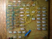
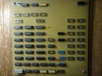
I have some new wiring to do, that on the Old system was on the Main Board, and Now is part of the Memory Board..

001.jpg 002.jpg

While doing this, I am watching the latest Video from the Edsac Reconstruction Project, this helps spur me on.. (I know this is not DEC..)
Nor am I using Tubes or Valves.. Can You Imagine wiring and making work a PDP 8i in tubes ??
https://www.youtube.com/watch?v=esDjyLJYVY8
I don't have near the problems that these Guys are working through, even though at times it may seem like it is just as Bad..

THANK YOU Marty
 
Last edited:
Back
Top