• Please review our updated Terms and Rules here

C64 IN PET S' CASE

Desperado

Veteran Member
Joined
Nov 25, 2017
Messages
6,827
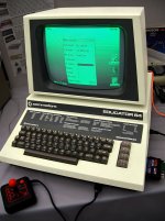
hello guys, how are you? we haven't heard from you for some time... I wanted to ask you for some advice, I'd like to insert a commodore 64 in the case of a cbm Pet ( like Commodore educator in picture )... keyboard and motherboard.. what worries me is the possibility of using the crt of the pet with the video output of the C64.. Do you think it is possible? A thousand thanks!
 

Attachments

  • 800px-Commodore_Educator_64_(standout_version).jpg
    800px-Commodore_Educator_64_(standout_version).jpg
    167.5 KB · Views: 66
Hello again.

Did you see my post the other week on your last PET problem? We had another PET with an identical fault to you - and we fixed it! I posted the device reference to change for you...

Back to your original questions:

>>> Do you think it is possible?

Anything is possible (given enough money and will)!

Within the C64 you have a SYNC+LUMA signal and a separate COLOR signal.

Of course, you can't get a colour screen out of a monochrome CRT (well, unless you use a colour wheel and then this is getting out of hand)!

You will have to find a circuit to extract (and generate) the HDRIVE, VDRIVE and VIDEO signal that the PET monitor is expecting from the C64 signal.

All this smacks of too much work to me - so I would look to replace the monitor and monitor electronics... i.e. gut the PET case and a complete refit. However, this would be sacrilege...

I would look to find a similar case to a Commodore PET and retrofit the C64 and an LCD panel to it.

Dave
 
Did you see my post the other week on your last PET problem? We had another PET with an identical fault to you - and we fixed it! I posted the device reference to change for you...
Great, unfortunately I did not see the post ... which device was faulty? I sold the faulty card some time ago and kept the case...

All this smacks of too much work to me - so I would look to replace the monitor and monitor electronics... i.e. gut the PET case and a complete refit. However, this would be sacrilege...

I would look to find a similar case to a Commodore PET and retrofit the C64 and an LCD panel to it.
Ok thanks!
 
I'd like to use a 64 with the green phosphor monitor of the pet but I should find a converter of the composite signal to horizontal and vertical signal of the monitor :(
 
Interesting idea... The hardest part is part is converting from black/white TTL to monochrome/grey(green)scale.
Are monitor schematics for the Educator 64 available?
Else you need to find a donor circuit from another monitor that accepts composite and is compatible with a 12" PET crt.
 
I wrote an email to Ruud Baltissen and he kindly sent me this scheme, saying that it is feasible as in educator 64. But I don't understand how to do it...
this is his answer:

"
Hallo Dave,


Do you think it is possible?

It certainly is because this is what Commodore did: the PET 64, also known as the CBM 4064 (https://en.wikipedia.org/wiki/Commodore_Educator_64). It was mostly sent to schools.

Attached is the schematic of the video board used in this computer. A little problem: I re-engineered the board when I owned one but later I sold it. But just now I discovered that I forgot to tag the pins. IMHO:
pin 7 = video
pin 4 = horizontal sync
pin 2 = vertical sync

You can search internet for more info.

Have fun! "
 

Attachments

  • Pet64-video.png
    Pet64-video.png
    23.6 KB · Views: 58
I found Ruud's post this morning - but haven't had any time today to post...

His circuit does exactly what you want! It takes the composite signal, strips it apart and regenerates the HDRIVE, VDRIVE and VIDEO signals for the PET monitor.

All you have to do is to build it and to get it to work!

Dave
Great Dave but Jp1 is on c64?
 
>>> Great Dave but Jp1 is on c64?

Yes. But this may not physically be marked as JP1 on the C64.

Ruud may have just labelled the two connectors as JP1 and JP2 on HIS schematic.

It doesn't necessarily follow that JP1 is on the C64 and JP2 is on the PET monitor...

Dave
 
>>> Great Dave but Jp1 is on c64?

Yes. But this may not physically be marked as JP1 on the C64.

Ruud may have just labelled the two connectors as JP1 and JP2 on HIS schematic.

It doesn't necessarily follow that JP1 is on the C64 and JP2 is on the PET monitor...

Dave
ok and Vcc is +5 V?
 
>>> ok and Vcc is +5 V?

Yes, always with 74-series logic.

Don't forget that there are also 'implied' 0V and VCC power pins on each IC package. The datasheets for the ICs detail these.

Dave
 
unfortunately i can't understand this:
 

Attachments

  • Pet64-video.png
    Pet64-video.png
    56.8 KB · Views: 35
They indicate the capacitors across the power supply (VCC and 0V). There is one 100nF capacitor fitted as close as possible to each IC (you have three ICs: 1 off 74LS08N and 2 off 74LS123N). These provide power (charge/current) to supply each IC when it switches. The other two capacitors (10uF) are to smooth the VCC rail.

The capacitors are drawn this way in the schematic capture program - but are placed close to the power supply (10uF) and ICs (100nF).

Dave
Very difficult for me :(
 
In which case this is beyond your current knowledge unless you learn more about schematics, IC datasheets and electronics in general.

Unless you an find someone locally to make it for you - but they may not have the knowledge regarding an old and ancient C64 and PET...

Dave
 
In which case this is beyond your current knowledge unless you learn more about schematics, IC datasheets and electronics in general.

Unless you an find someone locally to make it for you - but they may not have the knowledge regarding an old and ancient C64 and PET...

Dave
Please Dave, can you help me to realize this little board??
 
I wonder if this can't be simplified with an LM1881, LMH1980 etc. and some level shifting. The question still remains how the Educator 64 is different from the PET64 (shades of green vs. black/green only).

The easiest solution would be using the 4064 kernal and stick with the mono TTL video
 
Back
Top