• Please review our updated Terms and Rules here

C64 IN PET S' CASE

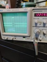
Are you sure channel 2 is on the top then?

You are also going to have to isolate one of those pulses in detail. Use the timebase, timebase X10 and X-SHIFT controls to see the detail of one pulse on channel 1 and channel 2.

Dave
 
This is ch2 with X10 time base setting
 

Attachments

  • 1695467494414..jpg
    1695467494414..jpg
    1.2 MB · Views: 2
  • 1695467542004..jpg
    1695467542004..jpg
    1.3 MB · Views: 2
  • 1695467560575..jpg
    1695467560575..jpg
    1.3 MB · Views: 2
Are you absolutely sure you are measuring the pins I asked you to?

There is something not right about what we are seeing on the oscilloscope screen. Reality can't be wrong - so there must be something we are doing that is!

Pin 2 (the B input) triggers on a low to high transition. Pin 13 (the Q output) should output a positive pulse of a length determined by C14 and R14.

The input (on pin 2) should NOT change when you adjust R14. The output (on pin 13) SHOULD change when you adjust R14.

Do you also have CHOP selected on the oscilloscope?

We can't continue from this step until we understand what we are doing wrong and we obtain sensible results...

Dave
 
So that signal is as expected.

However, the other channel is not.

Are you absolutely sure you have the CHOP/ALT button pressed in for CHOP? It looks out for ALT to me - but I might be wrong.

Also, the signal looks inverted to what I expect. You are on the SN74LS123 device aren't you?

It also starts BEFORE the low to high trigger event - so you have just invented a time machine to see into the future!

Let's have a look again at channel 1. Can you post a photograph of the IC and probe configuration please.

Dave
 
I can't really see where you have channel 1 connected to. Can you confirm which pin of the SN74LS123 it is connected to please.

What is connected to pin 4 of the SN74LS123 out of interest?

Dave
 
Back
Top