This is the problem - it is not as simple as 'wire from point A to point B'.
It involves measuring signals (pulses) with an oscilloscope and adjusting potentiometers correctly based upon the measurements.
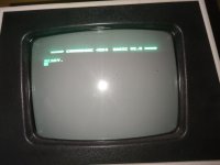
I have asked for measurements. Firstly, with the monitor working - but with the text too far too the left; and secondly the same set of measurements, but with the text correctly aligned - but with the noise.
The things to measure are the Q outputs from each monostable (4 off) and the VIDEO signal to the monitor itself under both conditions.
If the monitor is 'getting upset' then there MUST be an observed effect in in one (or more) of the signals from the interface board to the monitor.
It is as simple as that...
What I need to know is 'what has changed'...
It may be as simple as we need to adjust a potentiometer - but I don't know what
@Desperado has done to replace the fixed resistors with potentiometers.
Alternatively, one of the monostables may be 'on the edge' of stability and we may have to adjust the capacitor to compensate. We have to make sure that the capacitor and resistor values stay within the acceptable limits (based upon the datasheet) for the IC types we are using.
The only person in the universe (!) with this design of interface board is
@Desperado, so the only person in the universe that can make the measurements is
@Desperado...
Dave