• Please review our updated Terms and Rules here

Can a heat gun kill an IC, even if it was never directly in the path of the heat?

T-Squared

Veteran Member
Joined
May 29, 2011
Messages
657
Location
San Antonio, TX
I covered this partially in a different topic, but I put it here, given its connection to all electronics.

I think, last year, during my attempt at upgrading the memory of my Macintosh 128k, I accidentally killed the 68000 CPU.

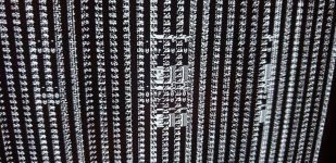
My reasoning is that the system no longer gives me the bell tone at startup (now a bad staticky screech), and the video is extremely garbled.

Even trying to use a 512k ROM set gives me bad images, even worse than before.

Should I clip out the old CPU and replace it?
 
My first thought is "it depends upon the temperature of the gun".

If the temperature is high enough to melt solder - then it may not have damaged anything - but the soldering could have become compromised.

Damage is going to be a function of both temperature and time. If you pointed a high enough temperature heat gun at a part (or parts) for a sufficient period of time then, yes, it could have done some damage.

Dave
 
Check the datasheet of the component(s). Many can not take high temperatures for more than a few seconds, which is even important when soldering. So basically: yes, it can. That's why people use aluminum foil or Kapton tape to isolate everything around from heat.
 
By the way, this is what I got when I first powered it on after modification:
 

Attachments

  • 20211104_165324#1.jpg
    20211104_165324#1.jpg
    3.1 MB · Views: 32
Plastic package ICs are particularly vulnerable to high temp work. Ceramic packages, less so. The subtle danger is that while you won't immediately damage the IC, but you could compromise the seals around the leadframe.
 
Why do you think that the symptoms indicate a CPU problem? What did you replace in your upgrade? If it was working before you messed with it, my first guess would be that the new improved parts, or installation of same, have some problem. The fact that it's trying to make a beep and trying to show the unhappy Mac on the screen makes me think the CPU is functioning quite well.
 
All these symptoms sound like messed up RAM, not the CPU. In the original toaster mac the sound generator works in concert with the video refresh hardware, in that the sound buffer is directly DMA'ed and played out through a (pretty crude) DAC. The same RAM problems that are trashing your screen are thus also trashing the sound.
 
What made me think it was the CPU was that the RAM tested fine. (I did test the CPU, I think, to see if the data lines were disconnected accidentally.)

Maybe, as some have said in the past, there was a specific RAM precision problem that the tester could not pick up on.
 
Yeah, it looks like a RAM issue that just affects one byte. I can't tell if it's the high or the low byte from the pic in #4, but it looks to me like the garbage is 8 bits (pixels) wide... The alternate columns look mostly OK though there are still a few glitches in there.

I'd check for solder bridges - visual check first, but then buzz out the address and data lines with an ohmmeter (assuming you don't have a logic analyzer available) and see if there are any shorts...
 
I suspect the address multiplexing is also damaged, given how bits of that sad Mac icon are scattered/duplicated around the screen. I do think you’re right that one of the banks isn’t getting read or written properly at all based on the “perfect” repeating columns of random garbage in between the “merely” garbled and misplaced stuff.

Without knowing exactly what mod was attempted on this board it’s difficult to guess exactly what got wrecked. (There are several different versions of both the 512k modification and the motherboard out there.)
 
Step one of this sort of thing (okay, maybe step 4 or so) is reversing whatever you did and seeing if it fixes the problem, of course.
 
By "this particular article," do you mean the Dr. Dobb's article that's linked in the one you posted? If so, did you make it past step (7) Test Motherboard successfully? If so, then we can be fairly certain that the problem is in your multiplexor mod. Can you post photos of your implementation of this mod? Maybe we can spot a problem if they're detailed enough...
 
Yes, the Dr. Dobbs article.

See, that's just it. My Macintosh is a later implementation of the Macintosh motherboard, which means that it already has the spaces for the address decoder and the components needed, instead of the pin-header space where you could later add a mod.

I looked over it several times for solder bridges, and I even flexed the motherboard a bit (not to an extreme), to be sure that the heat did not affect the layers inside.
 
I even flexed the motherboard a bit (not to an extreme), to be sure that the heat did not affect the layers inside.

So... you put it over your knee when it was running and looked for changes or?

To me it seems like the first thing you should check to rule out you baked the motherboard while heat-gunning off those Apple chips is, starting from one end of a row of memory chips, stick a continuity test probe into each pin of the first socket and then make sure you get continuity from that to the same pin in the next socket down the line. All pins except 2 and 14 should be in parallel in each bank; any gap and either your socket soldering is flawed or a trace in the motherboard got smoked. If *all* of those connectors pan out then you can trace the D and Q lines; for those I'd need to look at a schematic for the machine as to where would be reasonable places to probe for them.

And then, if that all pans out, then I guess we could start tracing the CAS and RAS lines to the multiplexing circuitry. Methodologically tracing this all backwards is the only way you're going to find the problem at this point.
 
OK, so the board is either: MC1023-00, 820-0086-00, 820-0086-B, or 820-0086-C.

There's a schematic for the 820-0086-00 here: https://www.folklore.org/images/Macintosh/schematic.jpg

My current theory:
I go back to the screen shot that shows one byte being (mostly) OK and the other byte being the bad one. It would only take one stuck address line (or enable line) on one chip to cause that behavior. It's unlikely that it is being caused by two address lines shorted together, as that would affect both bytes. Since all the address lines are in parallel for the 16 memory chips, I think the most likely case is a broken trace or bad solder joint on one of the memory chips. If we could determine whether it's the high or low byte that's bad, we could reduce the number of chips to check by 1/2...

Decoding circuitry is not likely to be the problem as all 16 RAM chips are enabled together. The CAS signal is different for the two bytes, however, and are generated by a PAL (1D).

Flexing the board is not likely to help locate the problem because the problem is not intermittent.
 
Since all the address lines are in parallel for the 16 memory chips, I think the most likely case is a broken trace or bad solder joint on one of the memory chips.

Blocks of the Sad Mac icon are being repeated in both the horizontal and vertical directions on the bank that's *not* broken, and since it's entire byte-wide chunks of the icon that are duplicated there is definitely something like a stuck address line affecting the whole bank at work here. In theory at least by doing a little math based on the positions of the repeated block patterns (like, for instance, how we see that same chunk of mouth and nose repeated some distance below the center of the screen, or how the right side of the Mac is doubled "immediately" and then repeated again some distance away) compared to what pixels *should* contain those dots (and where they would lie in the memory map) you could probably make an educated guess which address line is stuck, and whether it's before or after the multiplexer.
 
So... you put it over your knee when it was running and looked for changes or?

To me it seems like the first thing you should check to rule out you baked the motherboard while heat-gunning off those Apple chips is, starting from one end of a row of memory chips, stick a continuity test probe into each pin of the first socket and then make sure you get continuity from that to the same pin in the next socket down the line. All pins except 2 and 14 should be in parallel in each bank; any gap and either your socket soldering is flawed or a trace in the motherboard got smoked. If *all* of those connectors pan out then you can trace the D and Q lines; for those I'd need to look at a schematic for the machine as to where would be reasonable places to probe for them.

No, more like pressed areas while it was running, just to make sure it wasn't a bridge or cold joint.

I did check the continuity as well. I did almost anything that article asked. I don't know if I checked the Q lines, though. It was last year when I did this mod. In fact, I documented it at the time: https://forum.vcfed.org/index.php?t...g-macintosh-128k-memory.1230314/#post-1248855
 
Last edited:
Blocks of the Sad Mac icon are being repeated in both the horizontal and vertical directions on the bank that's *not* broken, and since it's entire byte-wide chunks of the icon that are duplicated there is definitely something like a stuck address line affecting the whole bank at work here. In theory at least by doing a little math based on the positions of the repeated block patterns (like, for instance, how we see that same chunk of mouth and nose repeated some distance below the center of the screen, or how the right side of the Mac is doubled "immediately" and then repeated again some distance away) compared to what pixels *should* contain those dots (and where they would lie in the memory map) you could probably make an educated guess which address line is stuck, and whether it's before or after the multiplexer.
Ah, yes. Well spotted. I think we may be looking at more than one address line being a problem - one affecting just one byte and the other possibly affecting both bytes.

Horizontally, it looks like it repeats every +1 and +8 and/or -7 and -8 words. Vertically, it looks like +7 and +8... I'd start with the 8, which would relate to A3 or RA3F from the schematic. It looks like RA3 is generated by IC 2F, a 74LS257, or the 74AS253 at 3F (depending on the state of the DMA signal) and becomes RA3F after passing through a 47 ohm resistor in RP2...

Me, I'd be inclined to drag out my logic analyzer to understand what's going on...
 
Back
Top