Hugo Holden
Veteran Member
I have also seen colleagues purchase EPROMS from the grey market only to find that they actually fell apart (literally) when they took them out of the delivery package...
Dave
I have learnt one very interesting thing about fake IC's. I have never found one yet where the IC or transistor is made of ceramic and has a significant amount of Gold plating.
One reason is that the ceramics are much more difficult to re-label and make it look convincing than plastic cased ICs'. It is really obvious if they get tampered with. Also the fakers putting dies in new IC's are generally working with epoxy, not ceramic.
But the other thing, the fakers cannot bring themselves to part with Gold, its like Gollums ring to them and they are addicted to it like Goldfinger was to his Gold.
So I'm very confident when I buy combination ceramic and Gold plated parts, that they are not copies, or fakes, that have passed through this dodgy IC faking industry. This is one reason I liked the look of those Czech military gold and purple ceramic 2716's, and was 100% confident they were the genuine vintage article, without a paper trail. Purplish grey ceramics are an even harder fake call, because they are less common too. Have a look at the unique package color again on post #43.
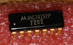
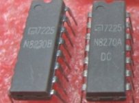
One other thing, even with epoxy cased IC's, there are some other things that give the game away. One is that some manufacturers had unique shaped epoxy cases. For example, if you look at early 74 series Motorola part, is has very characteristic rounded corners, not seen on other 74 IC packages. Early Signetics IC's used a unique light grey epoxy. Japanese IC's can also be spotted by their different package contours and indentations. So a lot of the time it is pretty obvious when things "don't stack up", checking very small details on epoxy cased parts, that the IC is a fake, clone or copy.
I have attached an example photo. Why is this Motorola IC a genuine original part, and not a fake ? Three things confirm it, the date code, it is consistent with the unique early Motorola epoxy package design, and the pins are gold plated.
Also, the vintage Signetics parts, obviously genuine parts: The fakers are not using this unique light grey epoxy, only Signetics did. They appear genuine and even have age appropriate corrosion on the leads.
Attachments
Last edited:

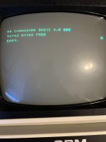

 , I wonder if I need to adjust the CRTC settings to compensate for the shift .. though that would need a revised EDIT rom