• Please review our updated Terms and Rules here

Cannot use EPROM to replace character ROM in 4032.

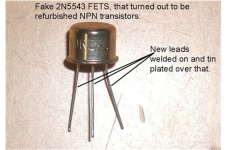
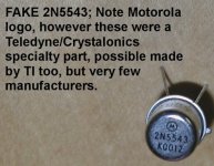
While we are on the topic of fakes, one of the fakes I once received was that of a high voltage jFet a 2N5543. The reason I caught this out was, there is transistor equivalent manual that mistakenly says its an NPN transistor, the fakers must have used that. But the astonishing thing was, it was a used transistor with short legs, they had welded on longer legs ! Then Tin plated over the welds !

The welds themselves were interesting, the wire faces were not cut perpendicularly to the wire axis, instead they were cut at an angle to create an elliptical face, presumably to increase the surface area. But, bending them with the pliers they fractured there and inspection of the weld faces indicated the join was incomplete & poor quality. Also, I don't think Motorola ever made this particular part.

But for the price of the part I could not believe someone went to this effort. I wrote to the seller and informed them if they were going to fake parts, at least they should select a similar part to fake and told them not to believe everything they read in a transistor equivalence book.
 

Attachments

  • IM1.jpg
    IM1.jpg
    55.9 KB · Views: 5
  • IM2.jpg
    IM2.jpg
    56.8 KB · Views: 5
Last edited:
Just chucking this out there... I wonder if a possible solution would be to both pull pin 21 on the EPROM and wire it to 5v (to get it off of /INIT), and then try replacing the /INIT pull-up with a slightly larger value than 1K. If /INIT really is acting as some kind of half-@**ed asynchronous clear signal it might rely on the total collective load/capacitance of all the inputs hanging off it as its "timebase" (instead of the separate capacitor you'd usually use for an R/C delay line), so without the "correct" load on it /INIT is coming up too fast.

When I say it out loud it sounds too dumb to be true, but this is a really goofy problem. Maybe that one Fujitsu 2716 just happens to draw in the same ballpark of current off VPP as the CS3 input of the stock MOS ROM, everything else is too much *or* too little.
Interesting, I'll give it a try. But before I do, I have made the following observations:

To set the theme, here is pin 24 (Vcc) on powerup, with ST EPROM:
5V-ST.jpg

Pin 21 with original (working) ROM:
Pin21-orig.jpg

Pin 21 with Fujitsu (working) EPROM:
Pin21-good.jpg

Pin 21 with ST (shifted) EPROM:
Pin21-ST.jpg

Pin 21 with TI 2516 (shifted & corrupt) EPROM:
pin21-2516.jpg

As an experiment I tried adding a 10uF bypass capacitor from pin 21 to ground. Had zero effect on screen appearance.
Pin 21 with original working ROM, still working:
pin21-orig-10u.jpg

Pin 21 with TI 2516, zero effect on shifting and corruption:
pin21-2516-10u.jpg

I also tried adding another 1k pullup resistor, making a total of 500 ohms. Again, there was zero effect on screen apearance.
Pin 21 original ROM. Still working:
pin21-orig-1k.jpg

Pin 21 TI 256, zero effect on shifting and corruption.
pin21-2516-1k.jpg

I must admit that if powerup behaviour and/or voltage level on pin 21 has an effect on screen corruption, then I would expect there to be some changes when the capacitor or resistor were added, but it turned out there was absolutely zero effect.

Edit:

I've now tried your suggestion to isolate pin 21 and connect it to Vcc. No change. I also tried increasing the value of R28 (/INIT pullup) from 1k to 4.7k. That also had no effect. Without the load of the character ROM, /INIT was a full 5V.

Just for fun, I tried removing the pullup resistor completely. /INIT then had a random squarewave signal varying between 2 - 3 volts. Despite this, the PET powered up OK and appeared to be stable, though I did not attempt to run any programs. Of course the problems with the character EPROM were still unchanged.
 
Last edited:
Interesting, in my PET I'm sure that when I lowered the 1k /INIT pullup to 100 Ohms, it affected the boot, but I will double check that sometime. I lowered it as an experiment, to allow for the drag down effect of the 2716. I don't recall adding a capacitor as an experiment though.

What would be interesting, with a dual trace is to compare the rise of /INIt with the 5V rail of most of the chips it is connected to.
 
Last edited:
I just double checked on my PET.

Well, the /INIT line is not greatly affected by the value of the pull-up resistor (I'm not sure why it seemed to be in the past, or I remembered that it had some effect).

I tried paralleling a 10 Ohm resistor with the 1k pullup, no effect ! Then I tried slowing it down with the 10uF capacitor from /INIT to gnd ..still no effect, the computer boots and functions normally on testing.

On the basis of this test, then, if the insertion of the 2716 for a Character ROM drag's /INIT below official logic high, or borderline, then it would appear reasonable to simply parallel a resistor with the original 1K pullup, of a value that achieves a logic high on pin 21 of the 2716 and the /INIT line.
 
Now I'm probably going way too deep into a rabbit hole with this, but there appears to be some discrepancies between my PCB and as it should be in the schematic.

My board is 8032080.

According to the schematics to this board, UD3, UE6 and UE7 all should be 74177s. In my board these are all socketed and they contain 74197s (though UD3 has a 74LS197). According to my tech data, both variants are pretty much identical, except that the 74197 is a bit faster and has a higher power consumption. I wonder if they are causing timing issues? UD3 does generate some of the system clocks.

My PET has always performed flawlessly, except I get screen corruption when running the 'No Pets Allowed' demo.

Guess I should swap these chips out and see what happens.

Edit: Tried putting 74177s back in all 3 positions, and no difference. Still have the problems with EPROMs, still have that corruption in 'No PETs allowed', otherwise the machine runs fine.
 
Last edited:
The schematics for my 8032080 board appears to list a number of modifications as shown here:
Screenshot from 2023-01-06 12-13-50.jpg

Most of them are 'cut & jumper' mods, and some seem to involve the timing and display parts of the PET.
My board does not appear to have any of these modifications.

Another user has reported that his PET with a later version board than mine appears to not have the same problems when using EPROMs in place of the character ROM.

I wonder if it is wise to try these modifications and if it will improve EPROM compatibility (and perhaps make my PET run 'No PETs allowed' better)?
 
It would be really nice when these mod sheets came out if they specified the exact purpose of each part of the mod and the overall mod. Or at least what problem is that is being solved and why the mod fixes it. So then we could decide if it was worth doing it, or if it solved a significant issue, or not. I try to avoid mods, unless they are very well thought out and explained and also factory. There can always be unexpected consequences (like I Robot's "random lines of code and unexpected protocols"). Its not a bad idea to try to put everything back to factory standard, if you are struggling with a fault. I think you should at least put the correct '177 IC's back in there.
 
It would be really nice when these mod sheets came out if they specified the exact purpose of each part of the mod and the overall mod. Or at least what problem is that is being solved and why the mod fixes it. So then we could decide if it was worth doing it, or if it solved a significant issue, or not. I try to avoid mods, unless they are very well thought out and explained and also factory. There can always be unexpected consequences (like I Robot's "random lines of code and unexpected protocols"). Its not a bad idea to try to put everything back to factory standard, if you are struggling with a fault. I think you should at least put the correct '177 IC's back in there.
I did try 74177s in those spots - luckily I have three of them. I guess a previous owner changed them at some stage.

I'm trying to figure out exactly what those mods do, and if I can try them non destructively, without cutting pins or tracks. Fortunately the previous owner had put many of the chips in sockets. The board had been rather corroded and needed proper cleaning, including under chips. I believe it had spent 30 years in a farm shed!
 
I think this was asked this already but I’m a bit fried to find the answer… have you tried swapping the CRTC in this machine? That it screws up when running “no pets allowed” *could* be a meaningful data point here?

There are a few pins on the character ROM that are directly driven by the CRTC (row selects and that high address line that’s connected for some reason), it seems like a real long shot but is it possible it’s somehow electrically on its last legs and the EPROMs just parasitically draw just enough more current to make it act up?
I have tried a different CRTC and there was no difference. All my CRTCs are Hitachi ones (including the one that came with the machine). I am aware that different brands of CRTCs can have subtle differences. I may have different ones in some other machines/cards I could try if the brand is an issue.

I understand that high address line that is controlled by the CRTC can be used to switch in a second bank of characters if the machine has a 2532 character ROM.
 
Last edited:
It is just so mind-boggling that anything you do with that socket can cause an off-by-one line alignment error.

Unfortunately a look at the 6845 datasheet confirms my rusty memory that all the interesting registers in the CRTC are read-only, so I guess you can’t read the contents of the start address register (R12-13) to see if that’s off by one. Have you tried poking the known-correct values into these registers after startup to see if it fixes the one-off problem?
 
I have tried a different CRTC and there was no difference. All my CRTCs are Hitachi ones (including the one that came with the machine). I am aware that different brands of CRTCs can have subtle differences. I may have different ones in some other machines/cards I could try if the brand is an issue.

I understand that high address line that is controlled by the CRTC can be used to switch in a second bank of characters if the machine has a 2532 character ROM.
I was able to switch to the second bank of characters using poke commands

poke 59520, 12 : rem set address register in CRTC to R12
poke 59521, 48 : rem this is setting bit 5 ( effectively performing a logical OR on 16 which is the default value stored in the register upon reset, ie 16 OR 32 = 48). To re-select the 1st bank poke 59520,12 : poke 59521,16
 
The schematics for my 8032080 board appears to list a number of modifications as shown here:
View attachment 1251181

Most of them are 'cut & jumper' mods, and some seem to involve the timing and display parts of the PET.
My board does not appear to have any of these modifications.

Another user has reported that his PET with a later version board than mine appears to not have the same problems when using EPROMs in place of the character ROM.

I wonder if it is wise to try these modifications and if it will improve EPROM compatibility (and perhaps make my PET run 'No PETs allowed' better)?
Yeah I read all of that and said WTF…. My board has some of these mods but not all. The fact they redesigned the board meant there was an issue.

I think have an 8032090 and will try that one to see if the problem still exists.
 
Yeah I read all of that and said WTF…. My board has some of these mods but not all. The fact they redesigned the board meant there was an issue.

I think have an 8032090 and will try that one to see if the problem still exists.
It seems those mods listed are instructions for rework after the boards are manufactured. They include things like attaching identification stickers and the piezo speaker, which are things my board has. However my board has none of the cut and jumper mods. In an attempt to determine how common modified boards are, I did a Google and looked at pictures of 8032080 style boards. Modification 14 on the list is very visible from the top of the board, so I looked for that (it also implies if it is done, the earlier ones would be too). It involved cutting the trace from Vcc to pin 3 of UC3. Out of the 4 or so boards I saw which had a clearly visible UC3, two had the trace present (like mine). One had it cut, and another had the trace missing entirely. It had a very slightly different board number, which I think was 802030.

Screenshot from 2023-01-06 12-13-50.jpg

Another thing I noticed is that the other major cut & jumper mods are 8 & 9. (They work together)
8 advises to isolate two ic pins, one is pin 21 UB3 (CRTC), the other is pin 3 UB1.
9 advises to jumper those isolated pins to other locations. Pin 21 UB3 to pin 8 UB6, and pin 6 of UC3.

The problem is that according to my schematic, if you isolate pin 3 of UB1 and then connect it to pin 6 of UC3, you effectively do nothing, as it was previously connected to pin 6 UC3.

According to the list in the top right corner, there are a list of engineering change orders for these revisions. Shame we don't seem to have them anywhere.
 
I agree, having the ECOs (like we do for the DEC equipment) would be really handy.

I see you are checking the schematic - what about the physical PCB though? It is just possible that the ECO was developed specifically for a bad batch of PCBs (and the track layout engineer was subsequently fired). The ECO then fixes the issue with the bad PCB. The schematic may well be correct.

Dave
After a lengthy examination of my board and the schematics, it appears that some of the modifications have already been incorporated, but others have not.

Modification 7 was not - but as it applies to the 8032, and my board was originally a 4016, I guess that was no surprise.
Modification 14 also was not incorporated. I'm going to try it as I can bend the pin out of the socket and temporarily connect it to the new location.

Looks like Commodore did change the PCB each time, this is why I did not see cuts and jumpers for the earlier modifications
 
Well, going down that little rabbit hole was a waste of time.
I temporarily incorporated the outstanding modification (14) to my board. No apparent difference at all.
The machine runs as before. Still good with the original character ROM, but screen shift/corrupted characters with an EPROM. Running 'No PETS allowed' still has occasional screen corruption.
 
Back
Top