• Please review our updated Terms and Rules here

Cbm 2001 Pet strange boot

Daver2.... It is very interesting that the byte which codes a Break is 00.

I just performed an interesting experiment on the CPU in my pet. When the CPU's data pins are left open DA0...DA7, they assume a low state and would be read by the CPU as low not high.

If there was a failure in the gating that controls the 74LS244 E9 & E10, which strobes the bus data onto the CPU (via the CPU R/W pin 34 of the CPU & buffer A10 and gate A5) the output of the 74LS244 would go into a high Z state when it should be transferring data to the CPU, the CPU would then execute a BRK as it would read an 00. ( also gates A3 & B2 would need checking).

Obviously if all that gating was working it could be reading a genuine 00 from the data bus, which could be corrupt (intermittent firmware- those over-voltaged 2532A's), or possibly PIA'a interfering but I think the pettester crashed with the PIA's out so probably not them, assuming that this is the same fault that caused the pettester to crash.
 
Hugo, E9 and E10 should be DISABLED. The ROM data bus is connected directly to the CPU data bus.

The DRAM and video RAM are gated through E9 and E10. I was trying to figure out how to disable E9 and E10. I think I can by pulling a signal LOW.

It is also possible that the CPU misreads an instruction byte or an address byte and causes it to vector to some random memory location where it starts to execute code (which may be data) and then just happens across a $00. This will cause the CPU to 'resynchronise' its execution at the BRK vector (back into valid code).

I am thinking that by putting my PETTESTER ROM into the EDIT ROM socket - if a BRK occurs it will cause a momentary access to the Kernal ROM that can be used as a trigger signal. However, the OP doesn't have any useful test equipment (e.g. a logic analyser) to ascertain what the CPU was doing at the time.

Dave
 
Check for activity on G5 pins 14, 11, 3 and 7.
I have this signal in normal conditions:

G5

PIN3: ???? LOW ( BUT GREEN LIGHT IS LOW INTENSITY ) AND SOMETIMES APPEARS RED LIGHT...
PIN7: LOW
PIN11: LOW
PIN14: LOW
 
>>> No Dave, i changed UD9 socket...not Cpu socket...

Thank you for the correction.

>>> Must i check in normal conditions or when is stucked please?

Certainly when the machine fails, but under normal circumstances to get a reference would be good.

I think your logic probe is not happy with the frequencies on these pins.

No way should G5 pin 11 be LOW though...

Dave
 
That was my 'test pin' for your measurements :) to see if they potentially made sense...

Let's see what happens on the G5 pins when a fault occurs shall we - but your test equipment may not be able to tell us much I am afraid.

Dave
 
That was my 'test pin' for your measurements :) to see if they potentially made sense...

Let's see what happens on the G5 pins when a fault occurs shall we - but your test equipment may not be able to tell us much I am afraid.

Dave
I measured now during fault but i have same measures.... :(
Pin 3 is strange....low signal but less intense than the others...correct?
 
Pin 3 is an 8 MHz signal - trying to attach any meanings to what you are viewing with a logic probe is meaningless I am afraid.

Basically, your test equipment is not telling us much.

Dave
 
Can be bad n555???? Sometimes happens that when i turn on i see machine code...
 
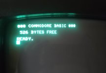
this is another weird screen on power up ... show less ram...if i reset i have normal screen...
 

Attachments

  • Schermata 2022-05-22 alle 17.36.10.jpg
    Schermata 2022-05-22 alle 17.36.10.jpg
    76.5 KB · Views: 4
The 555 is only responsible for the reset. If you see the 'random screen of garbage' on power up it can be the 555 - but this is not what you are observing.

The less RAM only tells me that something went wrong with the PET's memory sizing algorithm.

The trouble with these posts is that the Commodore BASIC ROM set is so complex that an errant CPU (for whatever reason) could give us a hundred (or more) random different effects from the same cause. This tells me nothing.

We need to go back to the PETTESTER to simplify the ROM code.

But, even then, I am not sure how you are realistically going to track down the problem with the test equipment you have.

I think, with this PET at the moment, it is a step too far for your skill set and your test equipment.

Dave
 
AC MILAN is 2022 Italian's Champion!!!!
But i am desperate for this Pet....
 
Hugo, E9 and E10 should be DISABLED. The ROM data bus is connected directly to the CPU data bus.

The DRAM and video RAM are gated through E9 and E10. I was trying to figure out how to disable E9 and E10. I think I can by pulling a signal LOW.

Dave
Yes, agree. And since the only way there would be byte 00 read would be if that was the actual byte presented by the ROM, either after it vectored away or in the program code where it should not be, unless say the E9 & 10 was pulling it low.

Since he doesn't have the tools, maybe the best thing I can think of at this point is something I suggested on 3 occasions before in this long thread. Make a complete set of good ROM's (from the 2532 not the 2532A) and fit those and soak test the machine. (If you advise him to do this he might actually do it)

If it fails again then you know for sure it is not intermittent data from the ROM's. If it does not fail you can then re-fit the other ROMs one by one to find out which is the culprit. If the fault remains ,then at least you know that the ROMs are good and there is something else failing, so it is a way of ruling out the firmware(ROMS) and concentrating on the support hardware.(I think he has tried a new CPU)

If a ROM fails to be selected (say its select line /CS1 fails to go low properly) the output is likely seen on the ROM bus D0......D7, to be 00. The logic driving those /cs lines could be monitored/checked. The /CS1 lines (pin 20 of the ROM IC's) could be checked on his scope to see if they were all going properly low, there could be a marginal condition where one of the IC's driving those lines is unable to pull it full low. (At least something to check)
Hugo i don't think that is a rom problem....fault happens also with original ud9 rom or only with pettester eprom....Maybe bad rams?
 
Forget BAD RAMs...

The DRAMS are isolated from the CPUs data bus by buffers E9 and E10. These could be faulty (dragging the data bus down when they shouldn't be) or they could be being enabled when they shouldn't be (thus corrupting the data bus).

What Hugo is saying is:

1. Use a TRUE 2532 EPROM (programmed correctly) instead of a 2532A (programmed incorrectly).
2. Make sure that the ROM is being enabled FULLY.

Hugo is also saying to burn a full set of Commodore PET ROMs - but I am disagreeing with him here. I would prefer Nivag's UD9 PETTESTER code only. We are allowed to disagree with each other of course...

However, in my opinion, you do not have the requisite test equipment to identify the specific issue that we are trying to look for.

Dave
 
Hugo is also saying to burn a full set of Commodore PET ROMs - but I am disagreeing with him here. I would prefer Nivag's UD9 PETTESTER code only. We are allowed to disagree with each other of course...
Ok i try to burn ud9 by nivag on 2532 eprom! Thanks
However, in my opinion, you do not have the requisite test equipment to identify the specific issue that we are trying to look for.
What can i do pleasE??? i am desperate...
 
And since the only way there would be byte 00 read would be if that was the actual byte presented by the ROM,
Hugo, the CPU was incorrectly executing in low RAM when it got the break instruction. In Message # 773 the M/L Monitor output shows the Program Counter at address $02C3. The other registers including the Stack Pointer seem OK. That area of RAM holds system parameters and probably has a lot of zeros.
But as to why it was executing in RAM??
-dave_m
 
Back
Top