• Please review our updated Terms and Rules here

Cbm 2001 Pet strange boot

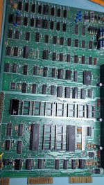
Probably not a solder bridge as its too thin and uniform, but it could be one of two things: Some man made lint, in which case it would be an insulator. Or it could be a dreaded Tin Whisker ! It would be worth checking between those pins with the meter.

One of the more difficult faults I ever tackled was a Tin whisker in one of my beloved 2465B scopes. It took me a week to find the problem. It developed an intermittent problem where the beam would randomly deflect downwards. There was a section on the main board (on the inaccessible surface of course) that had the whisker where there was no track coating. It is a lot of work to take that board out. I wrote up the story. Not long after I found out about a stack of main boards at a Tek scope repairer, that were deemed "unrepairable" and I'm sure these would have had the same problem.


On another occasion, one of my more modern LG workshop VDU's suddenly started acting as though somebody was intermittently pressing the menu button (like a Ghost in the machine). And at the same time the screen image changed contrast on exactly one half of the screen. But this time the penny dropped early, because two completely different parts of the circuit malfunctioned at once (that is a very big Tin Whisker clue). It was also a board proudly boasting "Pb Free" (thank God this is not allowed in Avionics).The Greens might pay to learn that the road to Hell is paved with good intentions. A whisker was linking two pins on a fine pitch pin processor IC. When I washed and scrubbed the board, the problem was much more extensive, a grey slurry of fine shorter whiskers came away from the surfaces, so many more faults were about to occur.
 
Last edited:
I can only go by what I did when I fixed mine - wouldn't continuity checks from the pins on the ICs the other side of those photos tell you it/where there are problems?

Colin.
 
I can only go by what I did when I fixed mine - wouldn't continuity checks from the pins on the ICs the other side of those photos tell you it/where there are problems?

Colin.
Yes they would. Desperado was asked to check the continuity of the IC pins & tracks and inspect the soldering, but whether all got done is uncertain.
 
Hy guys, my friend Antonio fixed the board and wrote this:

CBM PET s'board a friend of mine had been working on it for a while and ended up in a loop of the hateful ones where without help you can't get out, convinced that the CPU was good and nothing else was broken, an inexplicable malfunction on the data bus.
Testing the CPU on a test vic20 I was sure that the 6502 was broken, system PROM tests I found two broken ones, replaced all the white sockets known to be "disposable", fixed the anomalous tracks / welds, everything works fine.
the sockets must be removed as I explained in a previous post that is by pulling off the white plastic and then with the soldering iron the pins one by one so I am sure that the pcb remains intact, the new poor quality sockets are responsible instead of the anomalous soldering where the tin does not adhere to the terminal due to the chemical tin plating that peels off together with the tin and the heat, the latter must be sanded finely to expose the underlying copper, only in this way the welding will be optimal, I replaced the white sockets with excellent tulip shaped sockets, thanks to the friends of VCFED other problems have been solved by my friend of which 74ls244 and other of which I do not know, boh it works well.
Caradonna Antonio


Attachments

  • petter1.jpeg
    petter1.jpeg
    409.5 KB · Views: 9
Congratulations Desperado, and well done to your friend who has managed to get it working so quickly, you must be very happy and we are also very, very glad to see it working at last.

I assume you are no longer desperate? ;)
 
Yes, well done to your friend.

So, it was either as simple as a solder joint (or two) or IC sockets - both of which were explained to you by various people at various times.

So, you need to do a bit of homework now before embarking on the next 'project':

1. Read up on how to solder, how to clean off the solder flux and mess left behind after the soldering process (if any) and what a good and bad solder joint looks like.

2. Practice desoldering and soldering joints on 'gash' boards. Make sure you can desolder parts with the minimum of damage to the PCB and make sure you can solder competently with the least amount of heat/time so that you get a good and reliable solder joint with the minimum of damage and 'spatter'.

3. You need to become more proficient with your oscilloscope I am afraid. This is going to take practice. Bad solder joints and faulty IC sockets SHOULD have shown up on your oscilloscope with the tests you were performing. Unfortunately, you couldn't accomplish a suitable trigger point.

Clearly your friend has more practice with these kind of things, you just have to be patient and learn some of these techniques.

Nice to see your PET working again though!

Dave
 
Congratulations Desperado, and well done to your friend who has managed to get it working so quickly, you must be very happy and we are also very, very glad to see it working at last.

I assume you are no longer desperate? ;)
Yes desperation is finished ;)
Thanks to all for your precious help!
 
Yes, well done to your friend.

So, it was either as simple as a solder joint (or two) or IC sockets - both of which were explained to you by various people at various times.

So, you need to do a bit of homework now before embarking on the next 'project':

1. Read up on how to solder, how to clean off the solder flux and mess left behind after the soldering process (if any) and what a good and bad solder joint looks like.

2. Practice desoldering and soldering joints on 'gash' boards. Make sure you can desolder parts with the minimum of damage to the PCB and make sure you can solder competently with the least amount of heat/time so that you get a good and reliable solder joint with the minimum of damage and 'spatter'.

3. You need to become more proficient with your oscilloscope I am afraid. This is going to take practice. Bad solder joints and faulty IC sockets SHOULD have shown up on your oscilloscope with the tests you were performing. Unfortunately, you couldn't accomplish a suitable trigger point.

Clearly your friend has more practice with these kind of things, you just have to be patient and learn some of these techniques.

Nice to see your PET working again though!

Dave
Yes Dave, i need more experience :(
When i ll receive the board, I'll have to test his dual floppy drive ... hopefully fine;) Thanks again for your help!
 
Well done to your friend. Hopefully they can work with you on any future projects that I'm sure are going to come your way as I think the bug has bitten deep :)
 
Good evening guys!!!!
I am desperate now!!!
I connected my 3040 cbm dual drive to working 2001N Pet but when i turn on, i can see only the two red leds...central led remains off :((
 

Attachments

  • Schermata 2022-08-08 alle 20.20.03.png
    Schermata 2022-08-08 alle 20.20.03.png
    521.8 KB · Views: 3
It might not be the drive which is faulty.

It is not unusual for there to be a fault on the IEEE port on these old PETs and you will not notice it until you try to connect something to the port. The machine can have a faulty IEEE port and work perfectly well in other respects.

Now that the machine is working well enough to run BASIC commands there are some simple checks you can do using the BASIC POKE and PEEK commands to get an idea of whether the IEEE port is working, because the port has the unusual ability to read the state of its own output lines.

I'm sure others will be able to tell you the exact method, but for now, with the drive NOT connected, try this:

POKE 59426,0
PRINT PEEK(59424)
Result=?

POKE 59426,255
PRINT PEEK(59424)
Result =?

...Remember the address you're PEEKing is not quite the same as the address you are POKEing.

...59426 for POKE
...59424 for PEEK
 
That was quick! OK, so those results should have been 0 for the first check and 255 for the second check.

If we translate the first result you should have obtained to binary you have:

00000000

And if we translate the first result you actually obtained to binary we have:

00100100

Counting from data bit 0 at the right hand side to data bit 7 at the left hand side we can see that bit 2 (which represents '4') is '1' instead of '0', and bit 5 (which represents '32') is '1' instead of '0'. If you add 4+32, this gives you '36'.

So the bad news is that this is telling you that you have a fault on two of the data bits on the IEEE port and the data bits in question are handled by two separate buffer ICs, UA7 and UA8. What is more, the simple check you did just now did not check the UA9 buffer, so there may possibly also be a fault with that buffer as well.

There are further checks which Dave & company can guide you through to narrow down the exact fault and rule out the 6520 - for example you can try swapping another 6520 into the UC6 position to see if that changes the results of the check but in my experience so far the cause of problems like this has always been failure of the MC3446 buffers - however they are quite expensive and difficult to find so any work you can do to prove that they are responsible for the fault before ordering replacements would be good.
 
Last edited:
While we are still on this old thread:

SirriusH: Can you explain why there is an offset on the poke and peek addresses for this test ?

( PS: I can hardly believe that I missed getting the MC3446 buffers as spares for my PET as I have every other IC, so I ordered some. A very good seller for genuine vintage IC's who has these is SH-Halbleiter in Germany and they are on the Bay and Desperado could buy them from there too, if they are needed)

I think the MC3446's run of the same 5V regulator as the destroyed 7400 (with shorted input pins) ran off, that I think might have had a transient input-output short, so the MC3446's could have been damaged when that event happened, likely since it seems like at least two of them are defective. All IC's running from that 5V rail on the rear of the pcb I think a suspects for damage.
 
Last edited:
Briefly, one port of UC6 is used to write 8 bits out to the IEEE port data bus via two of the MC3446 buffers, and the other port of UC6 is used to read 8 bits in from the IEEE port via the same two MC3446 buffers. The data registers for the two 6520 ports are internally mapped to different addresses inside the chip, hence the need to write to one address, and read from another.
 
Briefly, one port of UC6 is used to write 8 bits out to the IEEE port data bus via two of the MC3446 buffers, and the other port of UC6 is used to read 8 bits in from the IEEE port via the same two MC3446 buffers. The data registers for the two 6520 ports are internally mapped to different addresses inside the chip, hence the need to write to one address, and read from another.

Thanks.
 
Back
Top