• Please review our updated Terms and Rules here

Cbm 2001 Pet strange boot

I would look at the H and V drive signals between the main logic board and the monitor first to see if they have changed.

This is a weird fault!

This PET is haunted I think...

Dave
 
I just looked at the video address counters, it doesn't appear they can run backwards, neither can the shift register run in reverse. So I cannot see right at this moment how it could be that the video map could be read out in reverse order.

If the vertical drive pulse to the VDU became abnormal inverted, because it is a direct drive system, not a sync pulse locked one, it might possibly reverse the direction of the vertical scan, and make it in error go from the CRT's bottom to top. So as Daver2 says check the vertical drive pulse on the scope to the VDU and see if it matches the zimmers waveform on the VDU schematic. It should be a negative going pulse about 1.2mS wide with a period of about 16.7mS.

It does show though that probably there is more than one remaining fault in this PET. The more that are present at the same time, the harder it can be to find each one.
 
Last edited:
I have just looked as well. The least significant 3 address lines of the character generator are also counting backwards as well (the characters are upside down) and that is just a simple 3-stage binary counter with (essentially) a single clock from the NEXT signal!

I have also observed that not the full image is there though. The 'top' 256 bytes (corresponding to the entire character set) is missing.

The characters being upside down is nothing that the CPU itself can influence, so that tells us that this is a different fault to the 'crashing' issue - and it is either in the video logic or the monitor - although how...

Need to sleep on that one!

Dave
 
Last edited:
I have also observed that not the full image is there though. The 'top' 256 bytes (corresponding to the entire character set) is missing.

Dave
That might be because if the vertical scan has reversed its polarity, its amplitude and linearity would be affected as the response of the vertical scan amplifier is different for flyback than for the scan time, so some of the scanning lines at the raster start(now at the bottom) could possibly be off the bottom of the screen and not visible. Looking at the characters, they are definitely stretched toward the bottom, (increased in height, abnormal V scan linearity) so this is almost certainly a vertical scan reversal situation in the VDU, with the most likely cause being, the V drive pulse it is being fed with has become inverted. Although the problem could be just inside the VDU, but probably less likely.

We need to check that vertical drive pulse on the scope !

After this fault is fixed, it is back to finding the other (hopefully last) fault.

PS: I have never seen a VDU spontaneously flip its vertical scan direction before. It is really only possible because it is a direct drive system in the PET VDU, not the usual oscillator locked system seen in most other VDU types, where it is highly unlikely that the sawtooth (ramp) generator in the vertical scan circuit could reverse polarity and still create a reasonable raster scan.
 
Last edited:
Although I wouldn't recommend it if you decide to socket and replace the RAM at least reconfigure the PET for 8 chip operation for the purposes of testing. That way you at least limit the amount of risky desoldering/soldering in the first instance anyway.

Alan
This is a very good idea.

If the 4116 RAMs are replaced, just do the I row and re-configure the jumpers to be a 16k pet and just use that row. If that works with new known good RAM IC's, then you can re-configure it to a 32k pet and either test the remaining RAMs in the J row with the pettester, or swap the CAS lines again to switch the two rows for testing. It may not be necessary to remove any RAM IC's in the J row at all.
 
Last edited:
We need to look at the video address generation circuit. Most likely the CPU put the data values, that correspond to the characters, into the correct places in the video memory map, or likely it would not be so orderly, but somehow the addresses which read them out of the video memory and clock them out of the shift register, have got flipped and the map (addresses) are being scanned out out in reverse, something like an up/down capable counter running in reverse........I'll look at the circuit. (This must be one of the more interesting faults ever reported in a PET and beats the pants off the recent "Ghost Writer" fault I had in a PET board which was due to a defective PIA)
This is a random fault, I don't always see it .... it also happened that he wrote some characters himself ... it seems that every time there is a different defect. Is it really possessed by some evil entity ??? ;)
 
This is a very good idea.

If the 4116 RAMs are replaced, just do the I row and re-configure the jumpers to be a 16k pet and just use that row. If that works with new known good RAM IC's, then you can re-configure it to a 32k pet and either test the remaining RAMs in the J row with the pettester, or swap the CAS lines again to switch the two rows for testing. It may not be necessary to remove any RAM IC's in the J row at all.

However, as you pointed out earlier it may stll be necessary to remove the row 'J' chips as leaving them in place could interfere with the 8 chip configuration. A little experimentation required I guess.

Alan
 
I am desperate...sometimes, during pettester, screen dissapears and come back also...
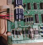
I noticed that the lower part of the board in the picture becomes very hot!
 

Attachments

  • Schermata 2022-05-26 alle 17.58.16.jpg
    Schermata 2022-05-26 alle 17.58.16.jpg
    132 KB · Views: 8
>>> I noticed that the lower part of the board in the picture becomes very hot!

It will. That is where the diodes are for the PET power supply.

>>> sometimes, during pettester, screen disappears and come back also...

That is interesting. That is the only part of what I am thinking about that didn't fit...

This is something that Hugo said ages ago - and I have been slowly 'mulling it around' in my brain and looking for evidence in your posts, photographs and videos - and I believe I am seeing many of the evidence of issues related to the /INIT signal being 'contaminated'.

You need to put your oscilloscope on UF10 pin 21 (the character generator) and monitor the DC voltage to see what it is doing...

Dave
 
Can you be a bit more specific? Too hot to touch? Hotter than the RAMs? Which component(s)? Capacitors? VR6? Rectifier diodes? Is Pin 3 of VR6 at -5V? As Dave says it's an area of the board that does get quite hot.

Alan
 
You need to put your oscilloscope on UF10 pin 21 (the character generator) and monitor the DC voltage to see what it is doing...
Hi Dave...ok i'll do this so i can see if voltage go down or up during fault! Thanks!
 
Have the the supply rails been checked for excess ripple somewhere along the way here? C63 on the -5V line looks physically stressed and may be failing. The 'scope can be used for this.

Alan
 
>>> I noticed that the lower part of the board in the picture becomes very hot!

It will. That is where the diodes are for the PET power supply.

>>> sometimes, during pettester, screen disappears and come back also...

That is interesting. That is the only part of what I am thinking about that didn't fit...

This is something that Hugo said ages ago - and I have been slowly 'mulling it around' in my brain and looking for evidence in your posts, photographs and videos - and I believe I am seeing many of the evidence of issues related to the /INIT signal being 'contaminated'.

You need to put your oscilloscope on UF10 pin 21 (the character generator) and monitor the DC voltage to see what it is doing...

Dave

One quick way to check the /INIT in case there is a borderline logic voltage or noise pulses on it, is to lower the value of the 1k pull -up resistor R12, simply by paralleling another resistor with it to reduce the value and allow it to source more current for the pullup.

So Dave_C78, try placing a 470 Ohm resistor or another 1k resistor in parallel with R12 to lower the overall value . ( R12 is the 1K resistor that sits between IC's UH6 and UH7) and see if anything changes with the fault/s.
 
I suggested this with the scope back in post #815, but we did not get a report back that it had been done.
Ok sorry tomorrow ill' do this!
So Dave_C78, try placing a 470 Ohm resistor or another 1k resistor in parallel with R12 to lower the overall value . ( R12 is the 1K resistor that sits between IC's UH6 and UH7) and see if anything changes with the fault/s.
Ok thanks!
 
Do what you are planning to do from post #857 FIRST.

Then read the following post: https://forum.vcfed.org/index.php?t...ollywood-syndrome.1238600/page-2#post-1258434

This is (was) an intermittent display issue on a Tektronix 4054 - nailed down (hopefully) to some faulty solder joints. After you have done what is in post #857 (and if it doesn't fix your problem) you need to examine ALL of the solder joints on your PET main board looking for similar faults to what was on the Tektronix machine.

Dave
Wow, this is a good job! Ok i'll check!
 
Back
Top