daver2
10k Member
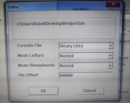
The contents of the BIN file you sent me are not what I was expecting I am afraid...

Dave
Dave
Please what can i do ???The contents of the BIN file you sent me are not what I was expecting I am afraid...
View attachment 1242671
Dave
I already programmed this eprom following Dave s'instructionsYou need to burn the top of the EPROM with the codes Dave showed
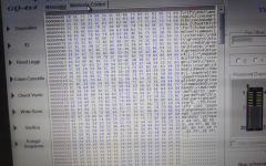
So the last two bytes in the EPROM are meant to be EE FF and it looks like they are 63 70
The 6502 gets its start address from the last two bytes at top of memory, so Dave has written a program to sit right at the top of memory starting at FFEE
Your EPROM should be programmed so the string of Hex codes Dave gave should fit right into the last bytes of its memory such that EE then FF are right at the end.

I can't send you a BIN file because I knocked up the assembler as a simple test and the BIN file is of no use to you.@daver2 please can you send me a .bin file?? Thanks!!
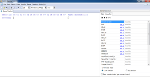
Daver,Code:FFEE A9 00 GO: LDA #$00 FFF0 8D 00 80 STA $8000 FFF3 A9 FF LDA #$FF FFF5 8D 00 80 STA $8000 FFF8 80 F4 BRA GO FFFA EE FF DW GO ; NMI FFFC EE FF DW GO ; RESET FFFE EE FF DW GO ; IRQ/BRK
!FFED A9 00 GO: LDA #$00
FFEF 8D 00 80 STA $8000
FFF2 A9 FF LDA #$FF
FFF4 8D 00 80 STA $8000
FFF7 4C ED FF JMP GO
FFFA ED FF DW GO ; NMI
FFFC ED FF DW GO ; RESET
FFFE ED FF DW GO ; IRQ/BRKunfortunately I can't in any way create this file or insert it in the programmer ... I'm desperate!
maybe i can try to burn a new 4k pettester ???
Ok thanks Dave!And what about my post #1,535?
In a morning please make sure you review all of the posts back to the last one you posted.
There is also some very important information (correcting an error in my test program) that you should be aware of in post #1,534 also.
Dave