Desperado
Veteran Member
- Joined
- Nov 25, 2017
- Messages
- 6,827
No signs of activity...always low signalMonitor the 6502 SYNC pin and apply a manual RESET to see if there are any signs of activity on SYNC at all. It will be brief...
No signs of activity...always low signalMonitor the 6502 SYNC pin and apply a manual RESET to see if there are any signs of activity on SYNC at all. It will be brief...
4-6: High37 - Input clock - 1 MHz.
39 - Output clock - 1 MHz.
6 - /NMI.
4 - /IRQ.
Yes but in this case is more difficult processIt all sounds like repairing a PET so far doesn't it?! Exactly the same process...
i used logic probe, ok now i check with scope!Did you use your logic probe or oscilloscope for this measurement? Your logic probe may not be good enough.
Yes Dave i can see waveform with scope on cpu pin 7 and on cpu pin 9 to 20.So, you now see that all test equipment is not equal!
If you look at the manual for the logic probe, it should have an upper frequency limit that it will work up to. You can't exceed this and expect it to work...
My next move on a PET would be to install a NOP generator and observe for pulses on CPU pin 7 (SYNC). Same thing here, plus look for pulses on the address decoder UB3 (74LS42) pins 1 through 7 and pin 9.
You should also observe the same square waves on the address bus of the 6502 CPU. Just the same as the PET!
Dave
yes pulses also on pin 9!And UB3 pin 9. Did you miss that one?
Dave
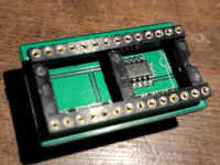
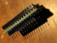
you can sent the attached gerber file to PCBway or jlcpcb.com (I found jlcpcb far better, faster and cheaper than PCBway) and ask them to make some adapter (tip: buying 10 will have the same price of 5...). They will work as 2364 to 2764 adapters; soldering a 74LS04 (SMD) on the PCB it will work as ROM-EPROM replacement for CBM disks that need an inverter on the /CS line; if not, you can simply jumper with some solder the pin #8 and #9 of the 74LS04 pad and it will work as 2364 to 2764 adapter for any other scenery (like C=64 etc.)Yes tomorrow!
It's possible burn eprom also for this drive?
Good evening!


no, im not sure that Rriot is ok....i have one Rriot replacement but i think that i need correct eprom firmware to burn!Are you convinced the RIOT IC is OK?
