• Please review our updated Terms and Rules here

Cbm dual drive 3040 disk - two red lights

If you are able to read the original PROM you can check the code you read out from it against the corresponding file on Zimmers. That way, you can find out whether the original PROM is OK or not.

If it is OK, then you don't need to spend time and money to create a replacement.

If you don't have a PROM reader but you do have a working PET then you might be able to put the PROM into a spare socket in the PET and use the built in machine code monitor - I think there is one? - to view the hex code in the PROM and compare it with the corresponding code file on Zimmers. This would depend on the FDD's PROM being pin compatible with the PET PROMs.
 
Last edited:
If you are able to read the original PROM you can check the code you read out from it against the corresponding file on Zimmers. That way, you can find out whether the original PROM is OK or not.

If it is OK, then you don't need to spend time and money to create a replacement.
I don't know if my eprom programmer willem 4x can read this prom :(
 
Are we all talking about the same part I wonder? Just to be clear (for educational purposes and the avoidance of doubt):

The RRIOT (ROM, RAM, I/O and Timer) is a 6530 located at UK3.

The RIOTs (RAM, I/O and Timer) are a 6532 and these are located at UC1 and UE1.

The ROMs are located at UH1 and UL1.

In order to replace the ROMs with modern EPROMs you will require an adapter (similar to post #96).

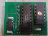
In order to replace the RRIOT at UK3 you will either require the very same part number of device (you can't program the RRIOT as such) or a 6530 adapter board (similar to http://blog.tynemouthsoftware.co.uk/2015/10/mos-6530-replacements.html). This little board requires a RIOT (6532) and a modern EPROM programmed with the requisite firmware. The firmware is available on the Zimmers website of course.

Dave
Yes Dave im talking about RRIOT on uk3, i have a replacement (on picture) for this ic but eprom is for a different drive...
 

Attachments

  • Schermata 2022-08-11 alle 11.56.02.png
    Schermata 2022-08-11 alle 11.56.02.png
    723.4 KB · Views: 6
Excellent, so we are all on the same page then...

Just wanted to make sure.

Dave
I downloaded correct bin file from zimmer but i think it should be a 1k file ... isn't it too small to fit into this eprom?
 
There are two (2) possibilities here:

1. Tynemouth used that size of EPROM as being a modern part, but only use 1K of it.
2. There is actually more than one RRIOT ROM image stored on the EPROM and there is some mechanism (e.g. links) for selecting the correct ROM image to use.

I am getting a DNS error - so I think the tynemouth website may have (temporarily) gone offline.

I suppose I should ask the dumb question - who's replacement PCB design is it?

Dave
 
In that case, only A0 to A9 are wired to the EPROM (10 address lines = 2^10 = 1,024 bytes = 1KB.

The other address lines are all pulled up to +5V (logic '1' / HIGH) - so you program the 1K RRIOT image into the top 1K of the 27128 (16K) EPROM. Although I note that you have a 2764 (8K) EPROM in yours.

Dave
Ok thanks so much...maybe can i add the file 8 times?
 
Dave if i wanna try to read the original RRIot with my eprom programmer, what type of device should i select?
 
No idea, but if you are going to try and read the 'real' RRIOT - then it is a 6530 (of some type) that you want.

And yes you can program the 1K multiple times (to fill up the EPROM)...

Dave
 
I burned a correct bin file in 2764 eprom and i used RRIOT replacement but i have same problem... i am not lucky with this cbm... :(
 
Look on the bright side, it is more likely now that it is not the RRIOT that is faulty!

Are you able to read the two ROMs with your EPROM reader, or doesn't it support them?

Dave
 
Look on the bright side, it is more likely now that it is not the RRIOT that is faulty!

Are you able to read the two ROMs with your EPROM reader, or doesn't it support them?

Dave
I don't know if it supports them ... which device should I select for reading on the programmer?
 
UH1 and UL1 are the ROMs I was thinking of...

Look at the schematic to identify the actual ROM type (not the Commodore part number indicating the programmed part).

Dave
 
UH1 and UL1 are the ROMs I was thinking of...

Look at the schematic to identify the actual ROM type (not the Commodore part number indicating the programmed part).

Dave
ah ok thanks!!
uh1 and ul1 are 2332 !
 
Looking at typical pinouts for MOS 2332 I see a complication where it was possible to specify the 'polarity' of the chip-enable pins at the time of manufacture, so some pinouts of the 2332 show pin 21 as being _CS2 (Active low enable) and some show it as CS2 (active high enable).

--If-- the ones used in the UH1 and UL1 positions in the drive are configured for both pin 20 and pin 21 = Active Low chip selects then it should be possible to read them by selecting device type = Texas Instruments TMS2532 or Hitachi HN462532 if either of those are available in the programmer's device list.

On those two EPROMs pin 20 is _G (Active low enable) and pin 21 is [High=Power down (High impedance)] and [Low=Power up / Enable outputs], when in read mode.

Unfortunately they can't be read as though they are the more common 2732 because:-

On 2332 / 2532, Pin 18 is A11 and pin 21 is active-low enable or active low power-up
On 2732, Pin 18 is active low chip enable and pin 21 is A11.
 
Back
Top