• Please review our updated Terms and Rules here

Cbm dual drive 3040 disk - two red lights

Looking at typical pinouts for MOS 2332 I see a complication where it was possible to specify the 'polarity' of the chip-enable pins at the time of manufacture, so some pinouts of the 2332 show pin 21 as being _CS2 (Active low enable) and some show it as CS2 (active high enable).

--If-- the ones used in the UH1 and UL1 positions in the drive are configured for both pin 20 and pin 21 = Active Low chip selects then it should be possible to read them by selecting device type = Texas Instruments TMS2532 or Hitachi HN462532 if either of those are available in the programmer's device list.

On those two EPROMs pin 20 is _G (Active low enable) and pin 21 is [High=Power down (High impedance)] and [Low=Power up / Enable outputs], when in read mode.

Unfortunately they can't be read as though they are the more common 2732 because:-

On 2332 / 2532, Pin 18 is A11 and pin 21 is active-low enable or active low power-up
On 2732, Pin 18 is active low chip enable and pin 21 is A11.
Thanks so much Sirius, my eprom programmer can read TMS2532 and HN462532!
 
Okay, but it may not work if those 2332 PROMs are configured with pin 21 as active-high chip select.

In the drive, it looks like the CS2 pins on those PROMs are driven by a buffered clock-out signal from the 6502. I don't know 6502 well enough to know whether the CPU will be trying to read the PROMs when that clock signal is high, or when it is low. No doubt Dave will know.
 
PHI2 = 1.

I am on my phone at the moment, but look at the next power of 2 larger EPROM and see if that chip select pin is actually a higher address line. If it is, the programmer will read half of the ROM as garbage and the other half as correct. The half that is read as correct is your entire disk drive ROM of course.

Dave
 
Okay, but it may not work if those 2332 PROMs are configured with pin 21 as active-high chip select.

In the drive, it looks like the CS2 pins on those PROMs are driven by a buffered clock-out signal from the 6502. I don't know 6502 well enough to know whether the CPU will be trying to read the PROMs when that clock signal is high, or when it is low. No doubt Dave will know.
I tried to read both eprom like 2532 or HN462532 but i always have verification failed!
more than half of the code seems to be empty ... for both roms .. Maybe as you say the programmer is not good!
 

Attachments

  • Schermata 2022-08-11 alle 20.49.30.png
    Schermata 2022-08-11 alle 20.49.30.png
    1.4 MB · Views: 8
I have my wires slightly crossed, on the 2532 pin 20 = active low output enable and pin 21 = VPP which needs to be at +5V in read mode, so if, as Dave says, the read takes place with CS2='1' that ought to work, as a programmer / reader will hold that pin at +5V when reading what it thinks is a 2532.

What you read does seem to have valid looking code at 0800-on, which chip was that you were reading, UL1 or UH1, and do you have a link to the matching code on Zimmers?
I was reading rom 901468-06 and this is zimmer s' file bin:
 

Attachments

  • 901468-06.bin.zip
    3.7 KB · Views: 3
Just checked back - OK so pin 20 = active low, pin 21 active high, that is actually good as it matches my (amended) idea of how the corresponding signals are 'polarised' on the 2532. So it should actually work, reading those PROMs as though they are 2532s.

Just waiting for Desperado to tell us which PROM (UL1 or UH1) he read in #124

I was reading rom 901468-06

Edit: Ok, just going to have a look at that.
 
Well that's interesting, I've just looked at that .bin file and the code you show at 0800 onwards IS the same as the code at 0800 onwards in the .bin file, so for some reason it is working to read the second half of the device correctly but not the first half.

What do you get if you read the other PROM as though it is a 2532? (and which BIN file is associated with that one)?
Same read...first half empty!
File bin associated is 901468-07.
 

Attachments

  • 901468-07.bin.zip
    3.9 KB · Views: 1
OK, this is sounding as though the programmer is (incorrectly) using pin 21 as A11 which would be correct for a 2732 but not for a 2532. I wonder if your programmer expects an additional adaptor to be used for these devices?

Try reading as Texas TMS2532 instead, see if you have the same result, first half blank.
 
Try reading as Texas TMS2532 instead, see if you have the same result, first half blank.
my eprom programmer have TMS2532JL OR TMS2532A....in both case i have always half blank...i am desperate... If i try to read original PROM from a cbm Pet, i read full screen!
 
And what type number is written on the original PET PROM which you are successfully reading? (The chip type, like 2332 or some other)?
 
Very hard to find a pinout diagram for the 6332 online but looking at how they are connected in the PET2001N for example I see that pin 21 (CS3) is held high and pin 20 (CS1) is used as active low, so that explains why those devices read OK as 2532 - and they should, because 2532s are drop-in EPROM replacements for 6332s.

However I don't see why the 2332 does not also work because on that chip pin 20 ( _CS1 ) is active low and pin 21 ( _CS2 ) should be held to +5V to read, just like on the 6332. I have to step away for a while, in the meantime maybe Dave can see what I am missing.

If we can't see what is wrong then it would be possible to make an adaptor which rearranges pins 18 and 21 to the right places so that the 2332 chip can be read as though it is a 2732. Don't try that without an adaptor though.
 
Let's continue tomorrow. Using a phone keyboard is rubbish!

Yes, do not use your ROMs in anything unless we know what we are doing and why. You don't want to destroy a perfectly good device by incorrect connections or power supplies.

Dave
 
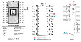
Just to help to kick start things tomorrow, here are the connections of the 2532 EPROM and 2332 PROM and 6332 PROM side by side. Unfortunately I could not find a pinout for the 6332 so I have had to snip that from the PET 2001N circuit diagram. You will notice that the power pins are the same pins on all three devices, as you might expect.

When a reader thinks it is reading a 2532 EPROM it should hold pin 21 (VPP on a 2532, Active high CS2 on a 2332, Active high CS3 on a 6332) at +5V - according to the 2532 datasheet it is necessary for this pin to be at +5V in read mode.

It should also take pin 20 (Power down when high / Active low enable on 2532, Active low _CS1 on 2332, Active low _CS1 on 6332) momentarily low during reads or may even hold them constantly low while it runs through all the addresses and reads their contents.

Going by Desperado's results it seems that when he tries to read his 2332s as 2532s, the 2332 is being held disabled during the first half of the read process and enabled during the second half of the read process.

2532_2332_6332_Comparison.jpg
 
One dumb question from what I am seeing in your photograph from post #24...

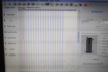
You appear to have Write and Verify ticked instead of just Read ticked.

Any reason why?

Write will stick 25V onto the ROM on pin 21 when it tries to write!

Yes, something is not happy with either the programmer or A11 (pin 18) on the devices.

Dave
Dave what you see on the right are the sequences, for the reading only I use the single buttons on the left .... for which the device is read only. I've always used this option for other eproms and it usually works ...
 
OK, thanks.

So, A11 (pin 18) appears not to be driven correctly by the programmer.

Can you just check the EPROM programmer documentation and double-check that you do not require an adapter for the particular device types you have selected to use to read the ROMs. It is unlikely - but let's rule that out as a cause.

EDIT: Just checked myself, both the HN462532G and TMS2532 do not require an adapter.

Dave
 
Back
Top