I find another problem on U9... With logic probe, pin 9 is low....

Shouldn t it Be high? The input on pin 8 is pulsing...
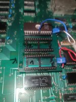
Why are you suddenly looking at U9? U9 is the 2K of RAM from 0000- 07FFF that's the entirety of the CPU RAM (other than video memory) that's in bank 15. U9 pin 9 is data zero, pin 8 is A0.
I'm getting really confused how all over the place this suddenly got. I thought where we left off was we had the CPU in this state:
1: A0 was pulsing
2: Sync was also pulsing
3: /G (pin 22) on the kernel EPROM was pulsing at a 2mhz rate
And the goal at this point was to try to figure out what addresses the CPU was cycling through. Are you *not* seeing the pulsing on kernel ROM /22 anymore and just randomly decided to jump to U9? Are you seeing pulsing on U9 pin 18? Because if you're not then that RAM isn't being accessed...
Although I actually should point something out here: if you're seeing a constant "0" on the D0 you measured there (it's in parallel with the D0 pins going to the EPROMs) and the sync pulse is running on the CPU that is a VERY strong sign the CPU is actually running the NOP ROMs chip; That ROM has only these values for the bottom 4 data pins, 0, A, C, and E, and
none of those have the zero bit set.
Can we go back to the Kernel ROM, after again making sure that conditions 1-3 above are set, and systematically do the following?
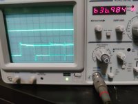
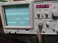
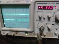
1: Place the probe that has the trigger function on it against A0, and confirm you get a square wave with your div setting set where it is in the previous pictures where you were on /G, IE, capable of measuring a 2mhz-ish beat. Take a picture of what you see; the periodicity of this signal is, unfortunately, not 100% regular so your scope *may or may not* lock on and give you a stable waveform; regardless of whether it does if your frequency counter is *any use at all* it should read about 500khz.
Do not freak out if instead of a square wave you see two parallel lines.
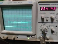
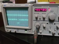
2: Repeat against A1. (Again, moving the probe that has the trigger on it.) This *should* be a square wave that in the general case is twice as wide as the first, so the frequency counter should be half as fast regardless of whether it fully locks on or not.
Again,
maybe you'll see two parallel lines. Don't panic.
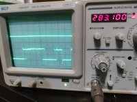
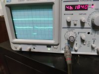
3: Move to A2. Again, frequency counter should be half as fast as the previous one if it's any good, and at this point turn the div/sec knob *one* click slower. *if* you're running the NOP ROM, again, the frequency should be half as fast as before, and, importantly, that "jitter" that we expect to see in the speed the address lines change when they "roll around" is going to start being of lesser magnitude than the width of the square wave we're looking for. So *if* you were seeing two parallel lines before it should start breaking up into something that's more obviously a jittery square wave.
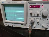
4: Again, move to A3. Again, frequency should be half as fast, and your scope should continue to have an easier and easier time locking on. Keep moving up through the address lines. The waves should keep getting wider, so as you move up you will need to, again, *one click at a time* slow down on the .div knob. (Again, if you started out with two parallel lines because the scope was getting thrown by the "turn around" it should be becoming less and less of an issue.) When you get to A3, for instance, a waveform should be around 71 Khz wide, so you probably will have the divs/sec knob turned to around 10 microseconds or so to get a couple transitions on the screen.
... Now I understand this is exactly what we told you to do earlier (and you did) around post
number 135 in this thread, but I'm hoping we have a better understanding of how the scope works and what we're expecting to see. At a certain point as we walk up through the address lines (and therefore down in frequency) your scope, even if it sucks, should be able to resolve a series of square waves instead of two parallel lines, and once you can be certain that's what you see you should see those waves double in width with every address line as you move up.
Keep moving up until you either make it through every address line or you hit one that's flatline up or down. That should never happen if the NOP EPROM is running as it should, but we don't know WTF is going on here so, well, that's your early out if you hit it.